A Field Perspective on Engineering Commissioning Resources
  • Home
    • What's New
  • Blog
    • Blog Support
  • SketchUp Models
    • SketchUp Resources
    • Bureaucratic Affairs Building HHW System Logic Exercise
    • Bureaucratic Affairs Building Scavenger Hunt
    • Chilled Water Plant System Diagram Exercise
    • The HIjend Hotel >
      • Chilled Water Plant Scoping Exercise
      • Ballroom AHU Scoping Exercise
      • Cooling Tower Scoping Exercise
  • Tools
    • Altitude Correction Factor
    • Economizer Evaluation Checklist
    • Eikon for Educators and WindLGC
    • Effective Duct Length Tool
    • Excel Third Axis Tool
    • Excel Time Value Conversion
    • Insulation Savings Tools
    • Logic Diagram Tool >
      • Logic Diagram Example - Discharge Air
      • Logic Diagram Example - CHW Plant 01
      • Logic Diagram Example - VAV AHU
    • Mixed Air Calculations
    • Monitoring Plan Spreadsheet
    • Pipe Friction Chart
    • Plot Digitizer >
      • Plot Digitizer Pump Curve Example
    • Square Law Spreadsheet
    • System Diagram Symbols
    • Thermodynamic Diagrams Spreadsheet
    • Universal Translator Data Analysis Tool
    • y = (m * x) + b Spreadsheet
  • Useful Formulas
    • Affinity Laws
    • Circular Equivalent Duct
    • Effective Duct Length
    • FT Guide Appendix C
    • HVAC Equations and Concepts
    • Hydraulic Diameter
    • Pump Power and Energy
    • "Square Law"
  • What's That Thing?
    • Cooling Towers
    • Pumps
    • Valves
  • Resources
    • Bill Coad's Writings
    • Data Logging Resources
    • EBCx Skills Guidebook
    • Energy Design Resources
    • Fisher Controls Valve Cavitation Bulletin
    • Functional Testing Guide
    • Honeywell Gray Manual
    • MCC Powers Bulletins
    • NBCIP Reports
    • PEC Tool Lending Library
    • PID Resources
    • Pneumatic Control Resources
    • Resource List
    • Scoping Resources
    • TAB Resources
    • Vintage Carrier Design Manual
    • VRF Systems
    • Williams' Wisdom
  • Videos
    • Bureaucratic Affairs HHW Logic Answers
    • Cooling Tower Flow Variation
    • Economizer Stratification
    • Functional Testing
    • Induction Principles
    • Monitoring Plans
    • CW Pump Deadheaded by Tower Lift
    • Ripple Effects
    • Testing a Pump
    • The Garden of Low Entropy
    • Variable Flow Systems
  • Training
    • Materials from Classes and Presentations >
      • ACEEE
      • ASHRAE
      • ASHRAE - Engineers Notebook
      • BCxA and NCBC
      • BEST Institute
      • Case Studies
      • ERDC 2020 RCx Academy
      • ELPNW
      • ICEBO
      • Marriott AEP
      • Magazine Articles
      • NAVFAC
      • Pacific Energy Center Design, Performance and Commissioning Issues Classes
      • Pacific Energy Center EBCx Project Review
      • Pacific Energy Center EBCx Workshop Series >
        • EBCx Workshop Series 12
        • EBCx Workshop Series 13
        • EBCx Workshop Series 14
        • EBCx Workshop Series 15 >
          • Student One On One Discussions
        • EBCx Workshop Series 16
        • EBCx Workshop Series 17
        • EBCx Workshop Series 18
      • Portland General Electric
      • U of W >
        • U of W Archive
    • On Demand Training >
      • Benchmarking UCA and Scoping
      • Loads and Psychrometrics
      • Induction Motor Principles
      • Introduction to Functional Testing
      • Scope of Work Documents
      • System Diagraming
    • Training Opportunities
  • Contact
    • Copyright and Permissions

Existing Building Commissioning Workshop Series 15 Materials

Picture

​As indicated on the main page, the true source for the materials for the existing building commissioning class workshop is the FTP site Ryan maintains.  If you need information regarding how to access it, you should contact him via e-mail at [email protected].  It would be desirable to include the words "EBCx Workshop Series Materials FTP Site Access" in the subject line to catch his attention.


​The materials below are the materials I provide for the portions of the workshop that I teach.   I am going to keep placing them here so that you can access them before class if you want and also to make it easy for Ryan to pull them back for the FTP site. 

​Note that most of the time, I include a "READ ME" file in the zip file with the materials and resources that describes what each of the files is about.
Session 2
Session 5
Logic Webinar 01
Session 9
Session 12
Session 3
Session 6
Logic Webinar 02
Session 10
Session 14
Session 4
One on Ones
Session 7
Session 11
Session 15
 
 
Session 2
During the discussion of the quiz questions, we spent some time talking about fans and fan applications and I mentioned a number of resources that I thought might be helpful.   A lot of the things I alluded to can be found in a blog post I wrote a while back about System Effect, titled System Effect–Dealing with the Point Where the Fan Meets the Duct.  So reading the post may be insightful in terms of understanding fans and their application.  But in the specific context of the class discussion, the following sections are applicable. 
  • There is a section that compares a plenum fan with a housed fan including a discussion of the potential efficiency penalty associated with using a plenum fan, and some of the things to consider when you apply them.
  • There is an example of how a plenum fan might be a better solution than a housed fan if the constraints of the mechanical room forced you to install the housed fan with a poor discharge condition.
  • There is a discussion of the different fan wheel types.
  • There is a discussion about how the field lessons you learn doing commissioning, in particular, existing building commissioning are important things to take back to the drawing board when you participate in a design review process.
I also mentioned a design brief that talks about how very early in the design process, you can use your knowledge about fan efficiency and system effect and some general assumptions and rules of thumb to negotiate with an architect to get the equipment space you need for an efficient HVAC system installation.  You can download that brief at this link.

Another valuable and free of charge resource for learning a lot about fans is the Howden North America’s Fan Engineering Handbook (a.k.a the Buffalo Fan Manual).  Follow this link find a blog post that looks at the resource and provides a link to where you can request the free, electronic copy.

Finally, the concept of equivalent duct length came up.  You will find more information on this and the related formula on the Effective Duct Length page of the Useful Formulas section of the website.
 
Session 3
2019-10-17_ebcx.zip
File Size: 49274 kb
File Type: zip
Download File

The file to the left contains the materials for the lab and lecture.
The files below are the follow-up materials I said I would provide during the class.  Note that you can also find a pump optimization case study on the Case Studies page of the website.   
pipe_clamp_photos.zip
File Size: 8494 kb
File Type: zip
Download File

pump_basics_and_optimization.zip
File Size: 11430 kb
File Type: zip
Download File

During class the pump affinity laws also came up and I said I would provide some additional resources on that topic.   You will find the information on the newly developed Affinity Laws page of the website, including some spreadsheet tools that will help you apply the laws if you have a digitized version of the pump or fan curve you are working with.  

If you want to know how to do that, you will find information about a free Java Applet called Plot Digitizer on the Plot Digitizer page of the website.  There is also an example of a pump curve created using Plot Digitizer in the form of a spreadsheet that you can download and use as a starting point for creating your own pump or fan curves on the Plot Digitizer Pump Curve Example page of the website.  This page also has an informal video showing how to go about digitizing a pump curve using Plot Digitizer.
 
Session 4

​Pre-class Materials

lab.zip
File Size: 45963 kb
File Type: zip
Download File

The materials for today's lab session are contained in the file to the left, including the two models you need for your homework assignment.  The assignment is to trace out the wiring for the level control system and try to untangle it into a ladder diagram format.  ​The ladder diagram format is what was illustrated in the October session lecture (Session 3)  where we discussed the logic that might be used to control the evaporator pump on a chiller.
It starts with slide 17 in the  Basic Concepts presentation.  Relay logic is physical logic and one of the ways I came to learn and understand the programming logic that we use for our control systems and try to convey with logic diagrams.

To get started, consider tracing out the wiring associated with the level control relay first (the top right blue relay).  Then, add the high and low level relay wiring to your diagram.  In doing the exercise, see if you notice a problem in the wiring circuit.  See also if you can figure out how the level control system works.  A hint is that the water becomes part of the logic.  And if you want to get a jump on the next class, see if you can convert the physical logic to DDC logic in the form of a logic diagram.

Next month, we will review the answer to the exercise in class and discuss how the level control system works.  Then, we will look at implementing the level control function using a DDC controller instead of the blue level control relays in the control panel.

​Follow-up Materials
follow-up.zip
File Size: 57887 kb
File Type: zip
Download File

The zip file to the left contains the follow up information that came up over the course of the class session.  It includes a README file that describes what the files and folders contain more specifically.
Filter Optimization

​
There seemed to be a number of people interested in looking at operating filters for best life cycle cost, which is what Arik did one of his lab sessions on.   You can get the general idea behind it by reviewing an NCBC presentation I did on the topic.   I also have a number of blog posts that explore it.

As you will find when you open the zip file, I have included the spreadsheet I have used to project potential savings using this strategy.  I am working on a better, more user friendly version of it.  So, the plan is to get that put together than offer a series of voluntary GoToMeeting sessions where I can walk you through it and help those of you who want to explore this option set it up for your system.  

To use the spreadsheet, you need a number of items of information, no matter which version we end up using.  So this would be a good time to start gathering that data.
  1. Make and model of all filters used by each system you are considering.
  2. The current methodology used to change the filters;  i.e. every 2 years, every 6 months, when pressure drop exceeds "x" in.w.c., etc. Note that prefilters may be changed more frequently than final filters.
  3. How many hours it takes to do a filter change for a given system, including getting the fitlers to the location, removing old filters and hauling them to the disposal location, cleaning the frames, installing the new filters, and verification of performance (typically required for clean rooms, some research facilities, and some surgical facilities).
  4. The hourly rate associated with the labor that is used.
  5. The cost of the filters currently being used.  Note that some vendors sell filters and others sell "clean air" (and in Portland, they usually include good vibes with the clean air).  Vendors selling "clean air" include all of the labor associated with item 3 in their quote.  So, you can't compare the price from a vendor selling filters with that from a vendor selling clean air.  For our analysis, we need to know the total cost of the filters with the labor separated from the raw filter costs.
  6. Logged data for the existing filter bank if possible.  This is the best way to establish the existing loading profile because it is based on the actual conditions of service and actual filters.   There are ways to estimate it from historical data from other sites that I have.   But if you have data from your site, that is by far, a better baseline.
  7. The method used to control fan capacity as the load changes or filters load and unload.   If the system is a constant volume system and does not have inlet vanes or a VFD to hold the flow constant as the filters load and unload, we will need to address that as part of the implementation plan.
  8. The method currently used to measure flow in the system, be it a flow meter, summing VAV flows or some other approach.  If there is not flow measurement strategy in place, we will need to address that as part of the implementation plan.
  9. The flow profile for the system.   If you have actual flow data, either by a flow measuring station or by summing terminal unit flows, then it would be desirable to validate that somehow.   If you do not have a flow profile, you will find some suggested ways to generate one on the Affinity Laws page under The Load Profile - A Key Element for Projecting Energy Use.
  10. The type of sensor that is currently used to measure filter pressure drop (magnehelic, photohelic, inclined manometer, analog transmitter etc.)  For the strategy to work we need analog data and if you do not have that capability, we will need to address that as part of the implementation plan.

Energy Recovery Calculations

​
There were several people interested in the efficiency of energy recovery processes.  There are actually two terms to consider; efficiency and effectiveness.   Effectiveness looks at how much of the maximum amount of recoverable energy was actually recovered.  Efficiency looks at that along with how much parasitic energy it took to do it.   The zip file includes the equations for both terms as well as tool I use to assess DOAS systems which could be modified for other recovery strategies like the run-around coils we were looking at.

If you need to do this sort of calculation, get in touch with Ryan and he will help you or get you connected with me for support.   If there are a number of people interested, we probably will use an approach similar to what I mention above for the filter analysis (a string of GoToMeeting sessions that interested parties can attend).

Answer Key for Scavenger Hunt Items
​

I plan to provide this as a part of the "What's That Thing" page of the website and will let you know when I have that completed.  It takes a bit of effort to get it set up and I am still working on it.

Picture
 
Session 5
2019-12-12_ds_ebcx_materials.zip
File Size: 26380 kb
File Type: zip
Download File

The file to the left contains the materials for the lab and lecture.
2019-12-17_monoflow_fittings.zip
File Size: 2323 kb
File Type: zip
Download File

In class we were discussing the heat pump loop where the supply and return connections to a heat pump seemed to be connected to the same line.
This placed the units in series in that some of the water leaving one heat pump would become part of the flow entering the next.  So, the question was to wonder what would cause water to flow through the heat pumps in the first place instead of simply bypassing them.   That led us to wonder if the diagram was wrong; i.e. if the units were actually connected in parallel across a set of mains. 

Certainly, this is an unusual piping arrangement.  However, there is a fitting that is manufactured by Bell and Gossett called a Monoflo Tee that is designed to allow a piping configuration like the system diagram showed. The tee has an orifice built into it that creates a pressure drop between the branch and the outlet, which will cause some water to want to go through the branch, all other things being equal. 

The tees could be applied individually or in pairs depending on how much pressure drop you wanted to create in the line between the tees (which diverts the flow to the device connected to the branch, in our case, the heat pumps if this fitting is in fact being used).   They look just like any other tee but have a red band painted on the outlet of the run to allow you to distinguish them in the field.

My primary exposure to them has been with finned tube radiation systems where they were applied to minimize the amount of piping required.  Instead of having to run two parallel loops around the perimeter of the building (one supply and one return) to feed finned tube radiation elements, you could run one line and and connect the elements in series.  The design needed to account for the fact that the upstream element reduced the water temperature entering the next element because the water entering the next element would be a blend of the system supply temperature water mixed with the water that was diverted through the finned tube and as a result, cooled.

If they are being used for the heat pump loop, a similar but opposite consideration would need to be taken into account.  In other words, if a heat pump was rejecting heat to the loop, then the unit downstream from it would see water that was a mix if the supply water temperature to the first heat pump blended with the warmer water created by the rejected heat from the first heat pump that was place into the portion of the stream that was diverted through the it by the monoflow fitting.   On a design cooling day, when all of the heat pumps were rejecting heat, this could limit how many you could place in series on a single loop.

The zip file contains the data sheets, submittal, and sizing information for the fittings in case you are curious to know more.  

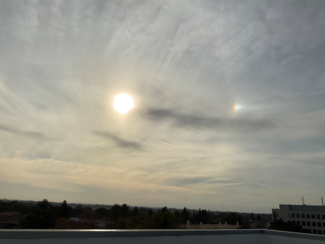
 Finally, while we are on the roof one of the days on site, some of you noticed an optical effect called a "sun dog".   It just so happens that the Cloud Appreciation Society's Cloud of the Month for December was a sun dog, so if you want to know this link will take you there.

If you look closely at the picture, you can also see another optical phenomenon called a halo, and this link to the CAS site will give you more information if you are interested.
 
Session 6
clay_valve.zip
File Size: 1490 kb
File Type: zip
Download File

lab.zip
File Size: 33720 kb
File Type: zip
Download File

reheat_coil_piping_package.zip
File Size: 1753 kb
File Type: zip
Download File

chw_system_diagram.pdf
File Size: 684 kb
File Type: pdf
Download File

chw_system_diagram_discussion.pdf
File Size: 576 kb
File Type: pdf
Download File

The files to the left are the materials we worked with in the January EBCx sessions.   Note that when I was on site initially with Ryan and James, I thought the valve packages associated with the reheat coils you saw in the interstitial space were PICs or Pressure Independent Control Valves.   But once I researched them some more, I realized they were not and there is an e-mail discussing that included in the reheat zip file

Note also that Ryan is planning to have me discuss the CHW system diagram for the College of San Mateo at some point.  But in the meantime, I include an .pdof of an e-mail discussion I was having with some of you that might shed some light on my perspective on it.
 
Logic Webinar 01

​Here is the video recording our our web session this morning along with the Logic Diagram tool with the diagram we built together in it.
logic_diagram_tool_web_session.xlsm
File Size: 1665 kb
File Type: xlsm
Download File

 
Logic Webinar 02

​Here is the video recording our our web session Wednesday afternoon along with the Logic Diagram tool with the diagram we built together in it.
logic_diagram_tool_v9_session_work.xlsm
File Size: 1661 kb
File Type: xlsm
Download File

 
Session 7
uc_davis_findings_01.zip
File Size: 86328 kb
File Type: zip
Download File

uc_davis_findings_03.zip
File Size: 140912 kb
File Type: zip
Download File

uc_davis_findings_02.zip
File Size: 81141 kb
File Type: zip
Download File

uc_davis_findings_04.zip
File Size: 205393 kb
File Type: zip
Download File

The zip files to the left contains the pictures I used for the discussion of our findings and/or interesting things we saw at UC Davis.  There is a text file in the third one that is my informal list of observations/comments behind the pictures. The picture numbers correspond to the list numbers.  The 4th file is the movie of the steam powered condensate pump.
Ryan and I would like everyone to at least take a look at the list in the text file, if not the pictures and select any topics you would like to have a focus session on, either in class or via an optional webinar or via a one-on-one session.  Send you selections to Ryan and he will compile a list and we will figure out how to best address your interests.  In some cases, there could be an existing resource we could point you at.
In terms of the follow-up information,
  • I will send out an e- mail as soon as I have the basic PID video recorded and posted on the website.
  • The design brief that has the case study about a project that had a higher than needed minimum flow rate to the zones is the one titled Design Review from EDR Site.PDF and you can find a copy of it on the Energy Design Resources page.  The case study starts on page 3.
  • The design brief that illustrates the procedure you could use to estimate the fan static required by a AHU is in the design brief titled Improving Mechanical System Energy Efficiency - Final.pdf, which can also be found on the on the Energy Design Resources page.  The example starts on page 9.
  • The blog post I mentioned about aliasing and trend sampling times is at this link.
  • The series of blog posts that I mentioned about using a condensate pump to validate a condensate meter or measure a steam load profile starts with this post.
With regard to the ASHRAE Standard 62 discussion, this link seems to give you a download of the ASHRAE spreadsheet.  Technically, I think it comes with the purchase of the User's guide so this could be not a totally legit download, just so you know.

Having said that, there is a company called Carmel Software that developed an App for ASHRAE that does the calculation.  There are versions for both IOS and Android operating system.  There is a modest cost to it ($20 currently) but that may be an affordable option for some of you and is less than it would cost to buy the ASHRAE Guideline 62.1 Users Guide, which would include a copy of the spreadsheet.  That said, I found the User Guide to be very helpful in terms of really understanding and applying the standard properly.   

I have the Carmel Software HVAC Toolkit Ultimate package on my iPhone and iPad and the apps work well.  There is a bit of a learning curve to figure out how to modify settings etc. But there are good tutorials and once you figure it out, they really are flexible apps.   that packages was in the mid $40 range when I bought it about 5-6 years ago, so probably a bit more now.  It includes the Guideline 62 app as a part of the package.
Finally, the filed below are, from left to right;
  • The College of San Mateo chilled water system diagram and related discussion, 
  • Three Trane Engineering Newsletters that touch on the pro's and con's of series chillers.
college_of_san_mateo_chw_system_discussion.pdf
File Size: 2147 kb
File Type: pdf
Download File

38-3_series_chillers_and_variable_primary_flow_plants.pdf
File Size: 771 kb
File Type: pdf
Download File

31-4_variable_flow_primary_revisited.pdf
File Size: 238 kb
File Type: pdf
Download File

chilled_water_system_design_learning_from_past_mistakes.pdf
File Size: 832 kb
File Type: pdf
Download File

Incidentally, the Trane Engineering Newsletters are good resources, so you may want to bookmark that site and if you are wondering about something, go check to see what they have to say about the issue.
 
Session 9
2020-04-16_class_materials.zip
File Size: 17334 kb
File Type: zip
Download File

The file to the left contains the materials for the April 16, 2020 session.   There will be an assignment that you will work on with a team between this session and the next.   For that, you will need the model of the chilled water plant that we have used previously, which you can download from the SketchUp Models - Chiller Plant Scoping Exercise page.
We will be doing a "What's That Thing" exercise in class built around some of the findings from our site visits.  I will upload those images after class so as to not give away any answers ahead of time.
2020-04-16_follow-up.zip
File Size: 8215 kb
File Type: zip
Download File

The folder to the left contains the follow-up information for the class, including information about pneumatic controls, bearings and bearing life, emissions factors, and the spreadsheet with the hand-off-auto switch calculations in it that we did in class, which is the same basic approach you need to use for your team assignment.
I intended to do more than just provide bearing and emission information but have a deadline pushing me pretty hard the next couple of days.  So I am providing the basic data and will follow up with more information next week.
If you want to see a process grade pneumatic product line, then follow this link to see what is available from Fisher.  You may also want to explore the pneumatic control resources page on this website.
 
Session 10
lab.zip
File Size: 78241 kb
File Type: zip
Download File

long_term_shut_down.zip
File Size: 4308 kb
File Type: zip
Download File

scopes_of_work_v3.pptx
File Size: 3296 kb
File Type: pptx
Download File

calculiation_review.zip
File Size: 8928 kb
File Type: zip
Download File

This is the information associated with my part of the class today other than one file, which I am still trying to get up here.

​This is the last file upload;  the one I was having trouble with.  The video was embedded in the PowerPoint and that was the problem.
field_trip_findings_v1.pdf
File Size: 62567 kb
File Type: pdf
Download File

Session 10 Follow Up
cut_away_package_unit.zip
File Size: 125157 kb
File Type: zip
Download File

cut_away_package_unit.zip
File Size: 125157 kb
File Type: zip
Download File

These are the pictures I mentioned that show the cut-away package unit at the PEC which may be helpful if you are working on a system diagram of a packaged unit.  Finding the parts diagram may also be helpful since they often have exploded drawings of the unit in them.
pump_insulation.zip
File Size: 11339 kb
File Type: zip
Download File

These pictures are the pictures I came up with that shows some examples of how insulators have dealt with providing access to chilled water pumps for maintenance with-out having the maintenance operation destroy the insulation.
scopes_of_work_v3.pptx
File Size: 3299 kb
File Type: pptx
Download File

These are a revised set of slides for the assignment that provide a bit more guidance than was provided in the set of slides that I uploaded earlier.
counterweighted_check_valve.zip
File Size: 9054 kb
File Type: zip
Download File

Tony and I mentioned a counter-weighted check valve in a chilled water plant that we are working on.  The zip file has a picture of it, catalog data for a similar valve (so far, we have not found the exact valve make and model), and the system diagram so you can see where the valve is in the system.
The valve was installed as part of an upgrade to the plant that allowed it to be quasi-variable flow primary only in that it prevents flow from bypassing the plant but allows flow reversal if the distribution loop flow is lower than the evaporator loop flow rate.  In the past, I have seen this type of valve adjusted to provide minimum flow (vs. simply opening fully when the flow reversal happens).
There were also a number of other resources that came up that I will link to next.
  • The Energy Design Resources Design Brief titled "Design Review" discusses many of the issues that exist with combined function valves (i.e. triple duty valves, which is the Bell and Gossett name for the product;  kind of like Kleenex is a brand of facial tissue).  It also includes a comparison of flow vs. pressure drop for different manufacturer's as well as a wide open butterfly valve with a wafer check valve.  This starts on page 11.
  • The NBCIP reports regarding CO2 sensors, including their "out of the box" and long term accuracy can be found on the NBCIP Reports page of the website.
  • In one of our e-mail discussions, I shared several resources that showed different valve types.   I have uploaded those resources below so you can find them more easily than digging through your old e-mail.
ASHRAE Handbook Valve Chapter.pdf
File Size: 3122 kb
File Type: pdf
Download File

piping_system_fundamentals_control_valve_chapter.pdf
File Size: 10243 kb
File Type: pdf
Download File

valve_cross-sections_from_flow_of_fluids.pdf
File Size: 1087 kb
File Type: pdf
Download File

2012-11-19_jenkins_bronze_valves.pdf
File Size: 4418 kb
File Type: pdf
Download File

piping_system_fundamentals_valve_and_fittings_chapter.pdf
File Size: 8217 kb
File Type: pdf
Download File

Tony's Materials
ebcx_series-xv_class-10_lab_hydronic_valves.pdf
File Size: 2656 kb
File Type: pdf
Download File

video_of_valves_1.zip
File Size: 27184 kb
File Type: zip
Download File

video_of_valves_2.zip
File Size: 28668 kb
File Type: zip
Download File

The files to the left are Tony's materials.  If you unzip them into the same folder, the links in his presentation should work.  Otherwise, you can just launch the videos.
A Few More Follow-up Items
domestic_water_systems_flushing_procedure.pdf
File Size: 1045 kb
File Type: pdf
Download File

wsj_-_printing_when_it’s_time_to_go_back_to_the_office_will_it_still_be_there.pdf
File Size: 69 kb
File Type: pdf
Download File

Here are a few more items that came up in class.  The flushing procedure is targeted at bringing domestic hot water systems back on line after being idle for a while (Legionella is a concern).
The other is the Wall Street Journal article I mentioned about the impact of Work from Home on the commercial real-estate market.
 
Session 11
scope_of_work_documents.zip
File Size: 478 kb
File Type: zip
Download File

2019-06-11_answer_example.xlsx
File Size: 8122 kb
File Type: xlsx
Download File

The files to the left are the  materials I will be using in the session today.
 
Session 12
The files below are the files you will need for the assignment
assignment_review.zip
File Size: 217623 kb
File Type: zip
Download File

The files below are the other materials I will be referencing today.  You may already have most of them because I originally was going to present most of this in May and then June.
2020-08-05.zip
File Size: 6293 kb
File Type: zip
Download File

field_trip_findings_v3.pdf
File Size: 31158 kb
File Type: pdf
Download File


​This is the video that shows the chiller in surge.  The video of the cooling tower flow was already posted with the materials from Session 10.

Note that the field trip findings file above is version 3, and has more information in it than version 1, which is what I uploaded for session 10.
chw_coil_selection_original_model.pdf
File Size: 87 kb
File Type: pdf
Download File

Picture
Picture
In addition to the information I provided in the presentation for you to use in your assignment, you will need the cooling coil selection information, which is provided to the left.

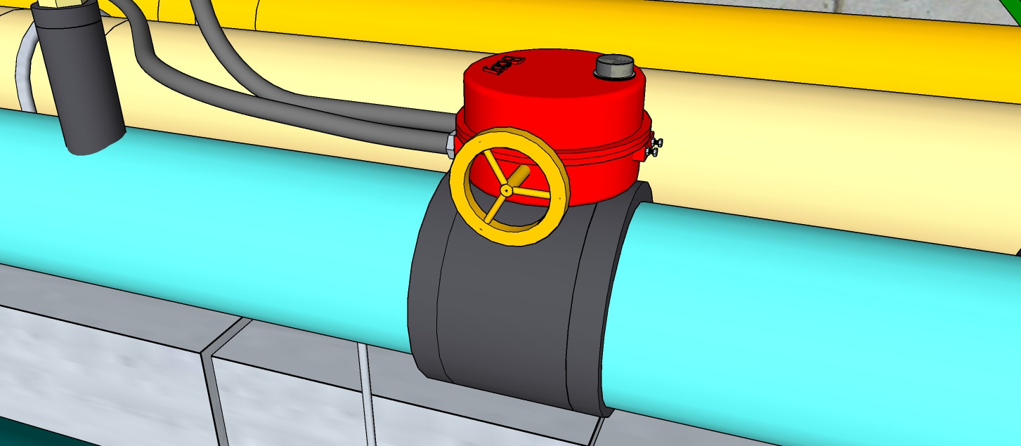
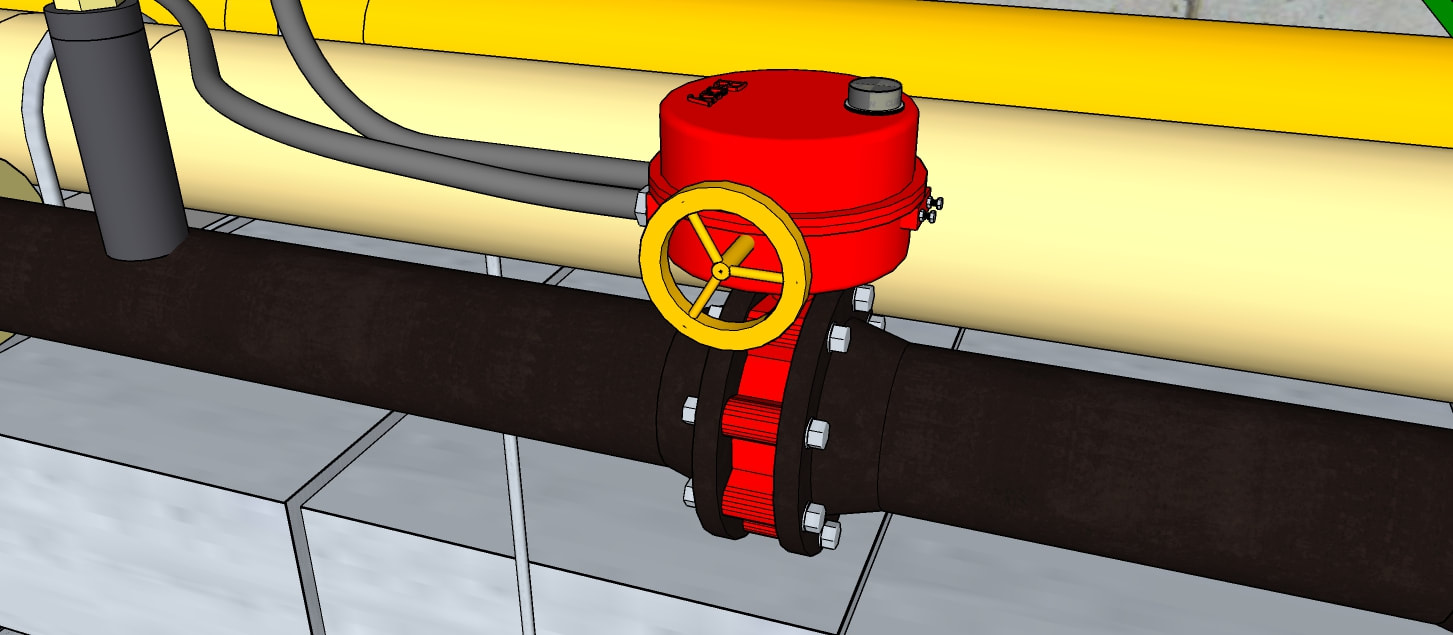
You also might need to know that the control valve for the cooling coil is line size, as can be seen in the images to the left and that the line size is 3 inch.  

For the pumps in the central plant, the line size is 8 inch.

You also may find the information on the Affinity Laws page to be helpful, especially the sections titled ​The Relationship Between Power and Impeller Speed and The Load Profile - A Key Element for Projecting Energy Use.
With regard t the energy savings we were discussing for operating one redundant fan at a time vs. running two at a lower speed, you will find a discussion of that on the Affinity Laws page in the section titled A Common Affinity Law Misapplication.
sectionk_environmental_controls.pdf
File Size: 1935 kb
File Type: pdf
Download File

With regard to the VFD enclosure cooling topic, the file to the left is from the Hubble company's electrical panel catalog and includes general information about the various options as well as information on their product line.
 
Session 14
Since the assignment was made, I have developed two resources that you might find helpful in terms of assessing the correct set point for the sensor in the remote location that will be used to optimize the control process running in the central plant to control distribution pump speed. 

One is a model of the CHW distribution system in the Hijend Hotel.  It is not detailed;  no service valves, hangers, etc.  But it does show the piping route and location of the air handling systems served by the loads and you could use it to help you assess the correct location for the remote sensor and what the set points should be used for the reset schedule.   I have also done work on the model of a typical guest room floor and have included that to give you a sense of how the fan coil units are installed.
​
The other is a more detailed version of the system diagram showing flow rates to the various loads and the distribution system as a schematic.  There are also tables that summarize flows on various risers and estimate the volume and length of the piping circuit.   Both of those resources are provided below.
hijend_hotel.zip
File Size: 7309 kb
File Type: zip
Download File

chw_system_diagram_v7.pptx
File Size: 3461 kb
File Type: pptx
Download File

 
Session 15
These are the materials for the class exercise today.  And, as I mentioned in the e-mail yesterday, you should also have your copy of the PGE Psych Chart available to work with.  You may also want a couple of paper copies if you prefer to draw on things with a pencil vs. electronically.
psych_exercise.zip
File Size: 23419 kb
File Type: zip
Download File


Home

Blog

Contact

Picture
A Field Perspective on Engineering - © 2017 Facility Dynamics Engineering, All Rights Reserved
(Contact Me to Check on Lefts or Any Other Questions You May Have about Permissions)