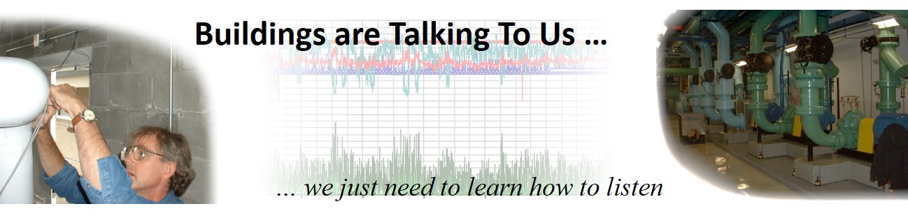
Centrifugal PumpsCentrifugal pumps are generally the most common type of pump found in buildings and their mechanical, fire protection, and plumbing systems.
If you understand how the merry-go-round works at the play ground, then you understand the basics of how a centrifugal pump works (or any centrifugal machine for that matter). In general terms, a spinning disc called the impeller, which is inside the pump casing, flings water from it's center to it's perimeter just like a kid on a merry-go-round is flung from the center to the perimeter as the merry-go-round spins. As you can see from the title of the picture to the left, you frequently need more than just the words "centrifugal pump" to describe one accurately. The gallery below will help you understand the more common variations on the theme that you will find in buildings. To use the gallery, scroll down until you find something that looks like what you saw out in the field. If you don't find what you are looking for, feel free to submit a picture of what you saw and we will see if one of the folks on our team can identify it and then add it to the appropriate gallery if it is something new. Use the navigation tabs at the top of the page to get back to the home page or a different part of the web site. |
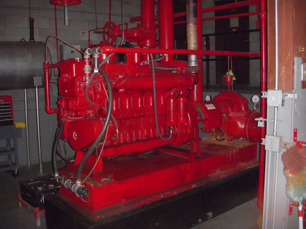
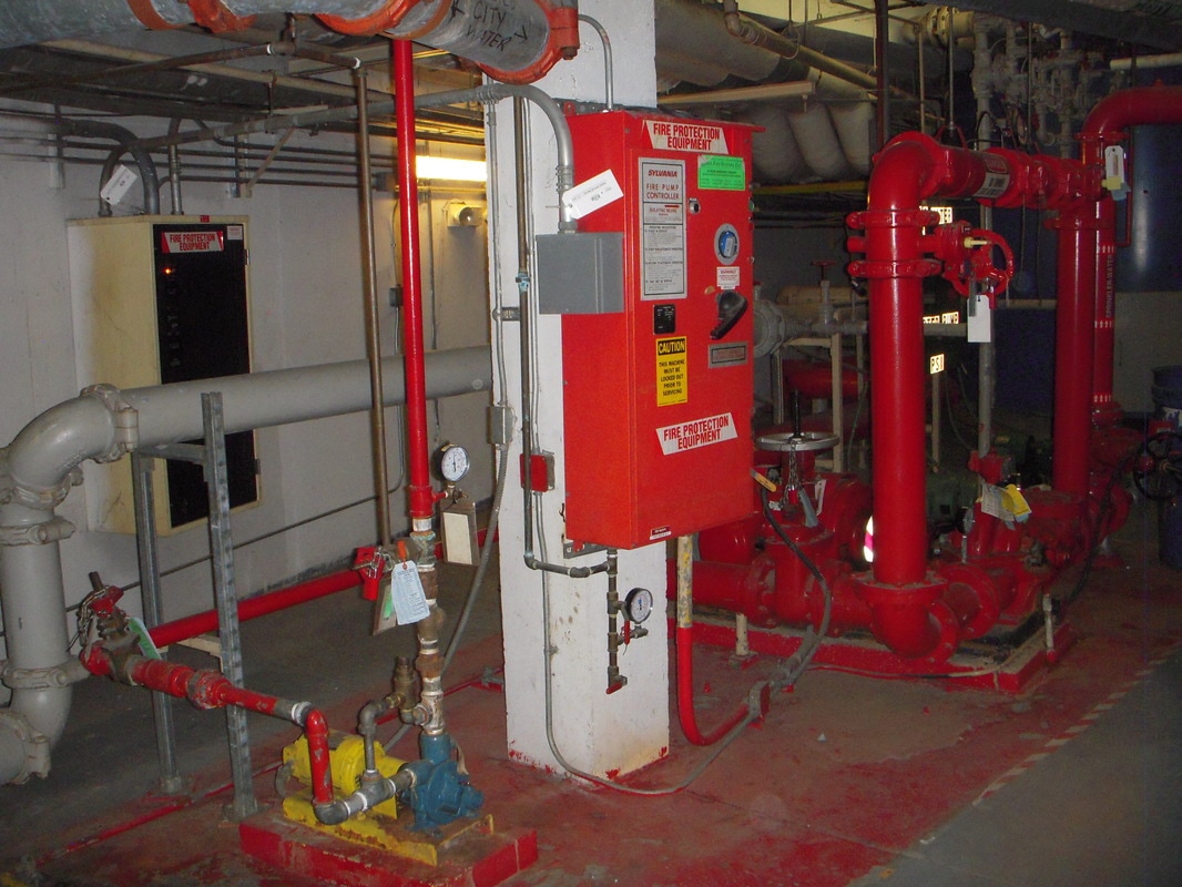
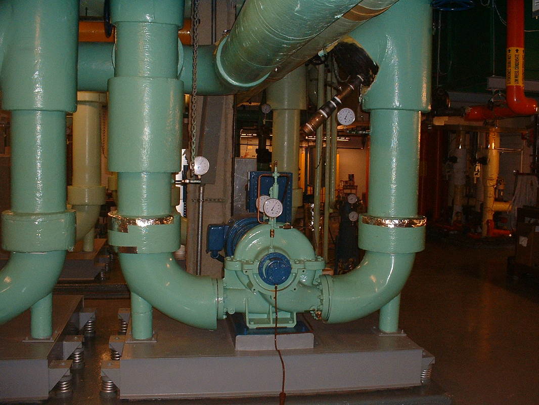
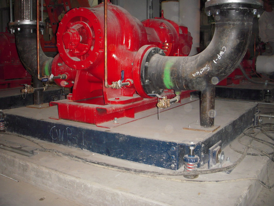
A Centrifugal, Double Suction, Horizontal Split Case, Engine Driven, Fire Protection Pump
Common Drawing Symbols for Pumps
|


|
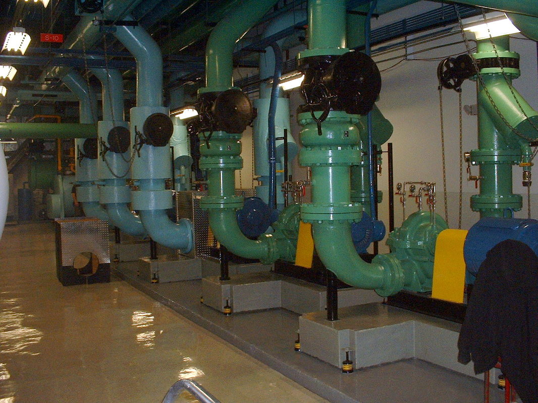
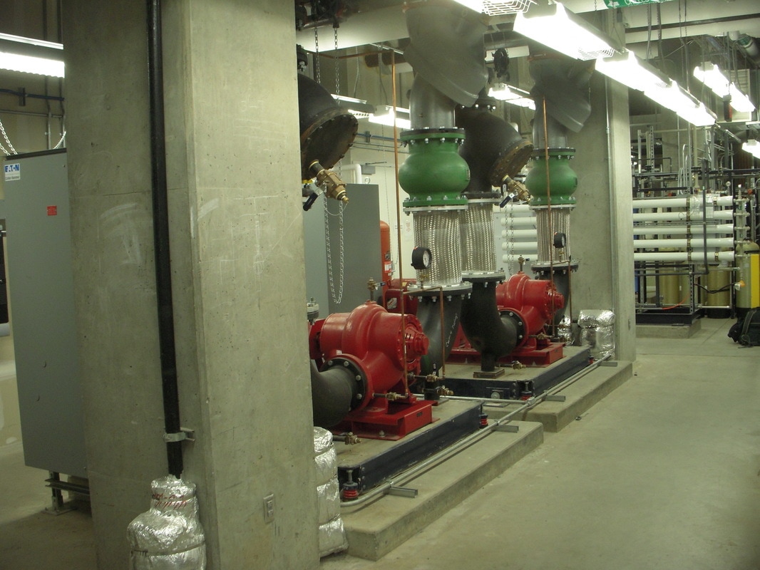
Engine Driven Fire Protection Pump The first picture to the left is a different view of the engine driven fire pump at the top of the page. The engine is the large hunk of metal to the right and in the foreground in this picture. (its to the left in the picture that brought you here). The pump, as you might expect is the part with the red pipes hooked up to it.
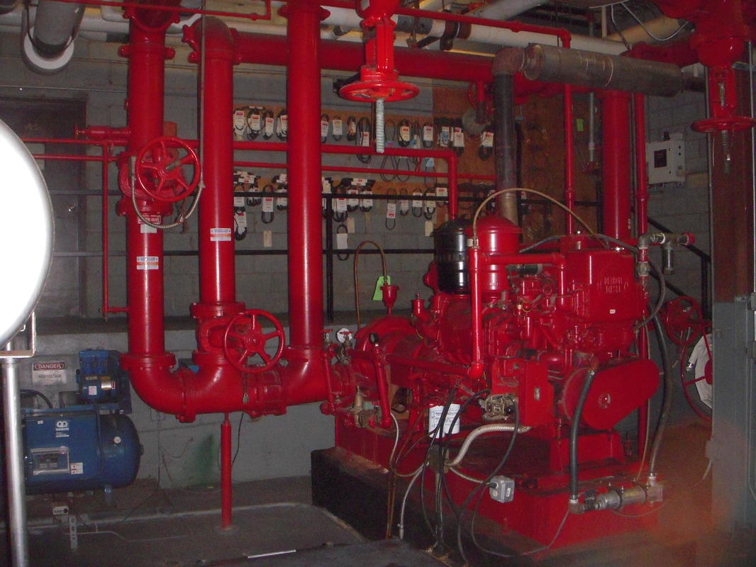
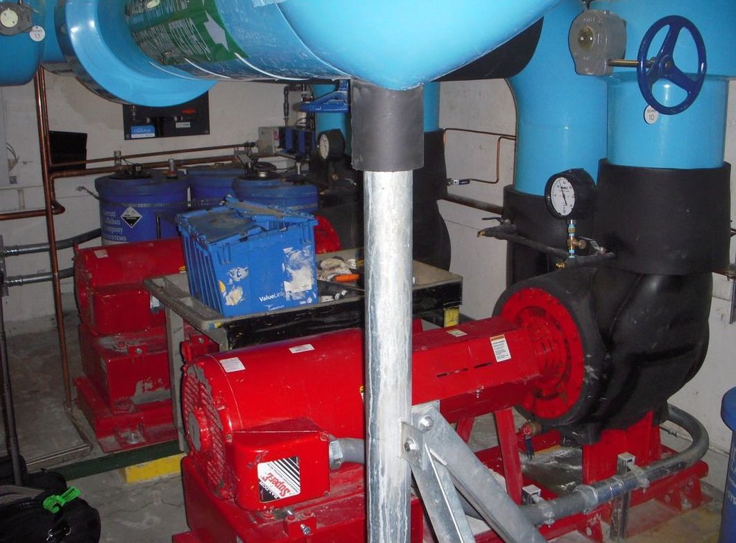
It is not at all uncommon for fire protection pumps to be engine driven because they need to work, even if a natural disaster has knocked the power out to the facility. The specific type of pump is a horizontal split case pump. You will find examples of that type of pump below. Not all fire pumps are engine driven; electric motors are quite common as illustrated in the second picture. If you go the electric motor route, there are a number of code provisions that are targeted at minimizing the chance of a loss of power to the pump in an emergency, even if the building is on fire. Virtually any piping system will have a few leaks and fire protection systems are no exception. While you absolutely want to start the fire pump if the source of a leak is a sprinkler going off, which can also cause the fire department to "roll the trucks", it is also desirable to not start the fire pump if a small leak at a fitting causes a loss of pressure. To prevent unnecessary fire pump starts (and the $10,000 fines associated with "rolling the trucks" from the local fire department when there actually was not a fire), virtually all fire protection systems that have a fire pump also have a "jockey pump". A jockey pump is a small pump selected so that it can easily make up water to accommodate for minor leaks, thus preventing an inadvertent fire pump start. But the pump is also selected so that if a sprinkler head were to go off, meaning there was an actual fire, it could not provide adequate flow, which would cause the system pressure to drop and (legitimately) trigger the start of the main fire pump. |
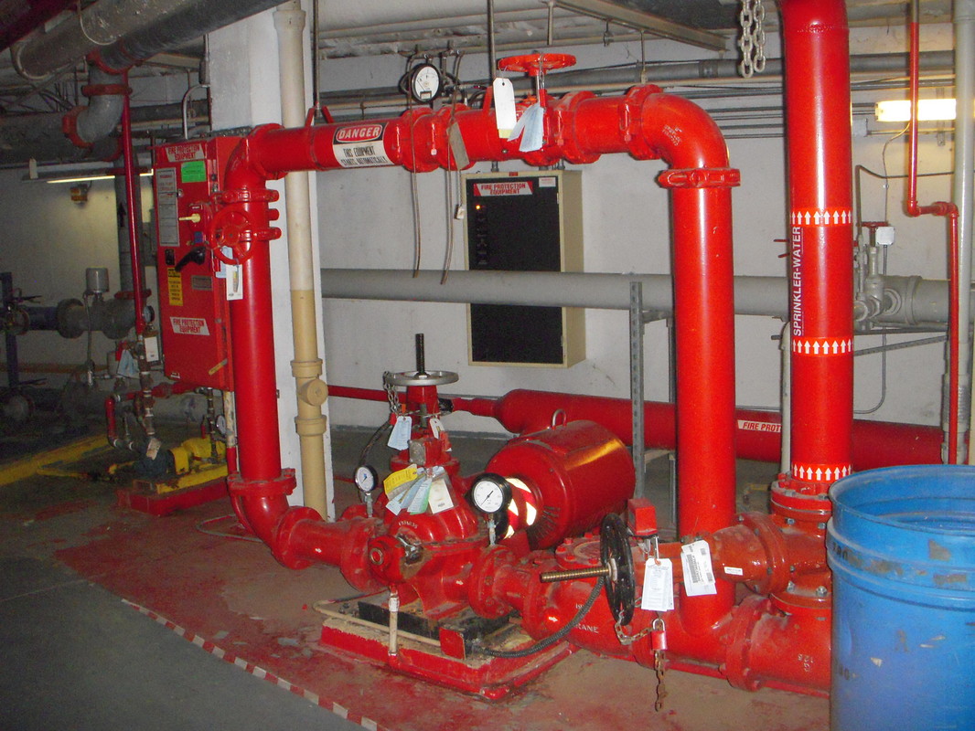
The third picture has a jockey pump in the fore-ground; its the small blue pump with the yellow motor. The picture is simply a different perspective on the second picture. The red box on the column is the fire pump controller, which manages the whole affair.
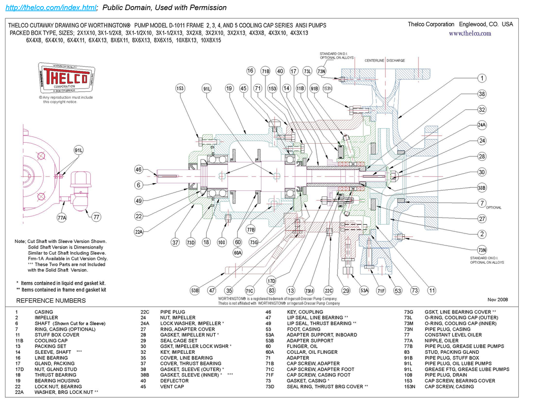
By code, fire protection pumps are required to have packing gland type seals. That is because the likelihood of a catastrophic seal failure is less than it would be for a mechanical seal. In other words, the life safety folks figure that it's better to waste a little bit of water due to poor packing gland maintenance than to risk loosing the ability to put out a fire due to the failure of a mechanical seal.
By code, fire protection pumps are required to have packing gland type seals. That is because the likelihood of a catastrophic seal failure is less than it would be for a mechanical seal. In other words, the life safety folks figure that it's better to waste a little bit of water due to poor packing gland maintenance than to risk loosing the ability to put out a fire due to the failure of a mechanical seal.
|
End Suction PumpThe pumps in the pictures to the left are end suction pumps. The impeller associated with each pump is a spinning disc inside the large round part with the pipes hooked up to it.
The second picture will give you a sense of what an impeller looks like. Water flows into the hole in the center and then, because the disc is spinning, it is thrown to the perimeter by centripetal force and exits the impeller at that point. The part of the casting that collects the water flung from the perimeter of the impeller and directs it to the discharge pipe is called the volute. In the upper picture, its the sort of spiral shaped part connected to the pipe on the far right, which is the pump discharge. If you consider the mechanism by which water moves through the pumps impeller (based on fundamental principles, just like the merry-go-round) and then recognize that the impeller has to be oriented in the larger portion of the casing in the first picture with its inlet towards the foreground in the picture, then you will likely conclude that the pipe in the foreground in the upper picture is the inlet of the pump and the pipe to the far right (the one with the blue thing in it) (its a check valve) is the discharge pipe. Since the inlet pipe enters one end of the pump, the pump is called an end suction pump. |
The details of the volute's shape and orientation relative to the impeller play a role in the pump's efficiency (among other things) as does the configuration of the vanes in the impeller. The relative diameter of the center or eye of the impeller to the perimeter of the impeller and the thickness of the impeller are clues regarding the pump's performance characteristic.
- Pumps that have relatively thin impellers with a large outer diameter relative to the eye of the impeller are generally intended to move smaller volumes of water but produce more pressure (often referred to as "head").
- Pumps that have relatively thick impellers with a small outside diameter relative to the eye of the impeller are generally intended to move larger volumes of water but with out producing as much pressure.
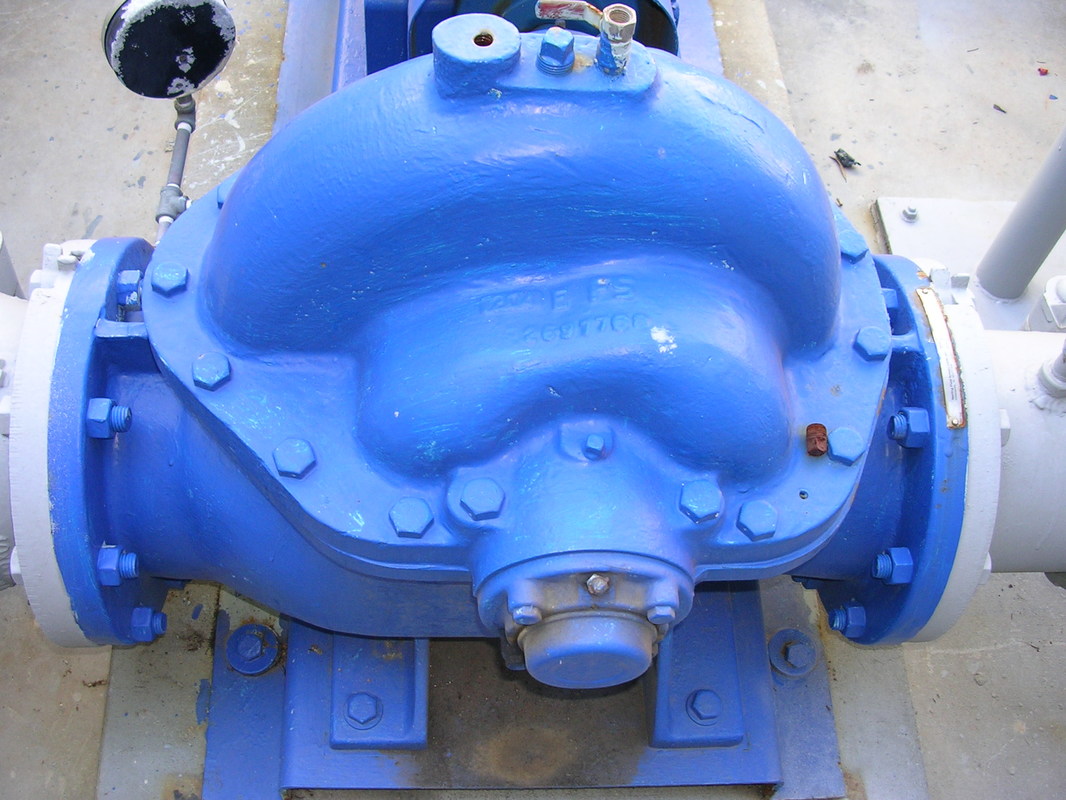
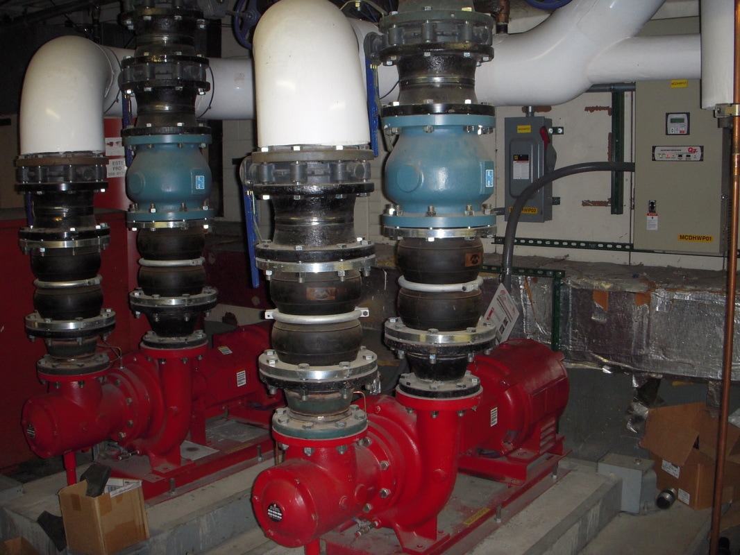
Double Suction, Horizontal Split Case Pump
|
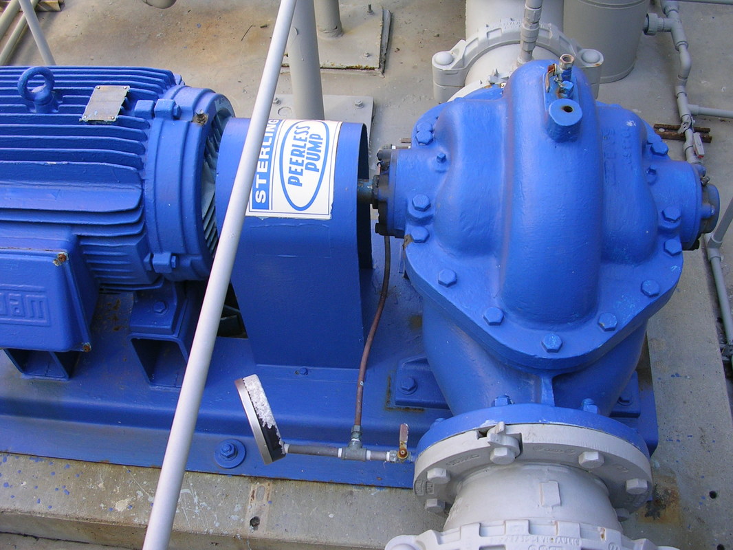
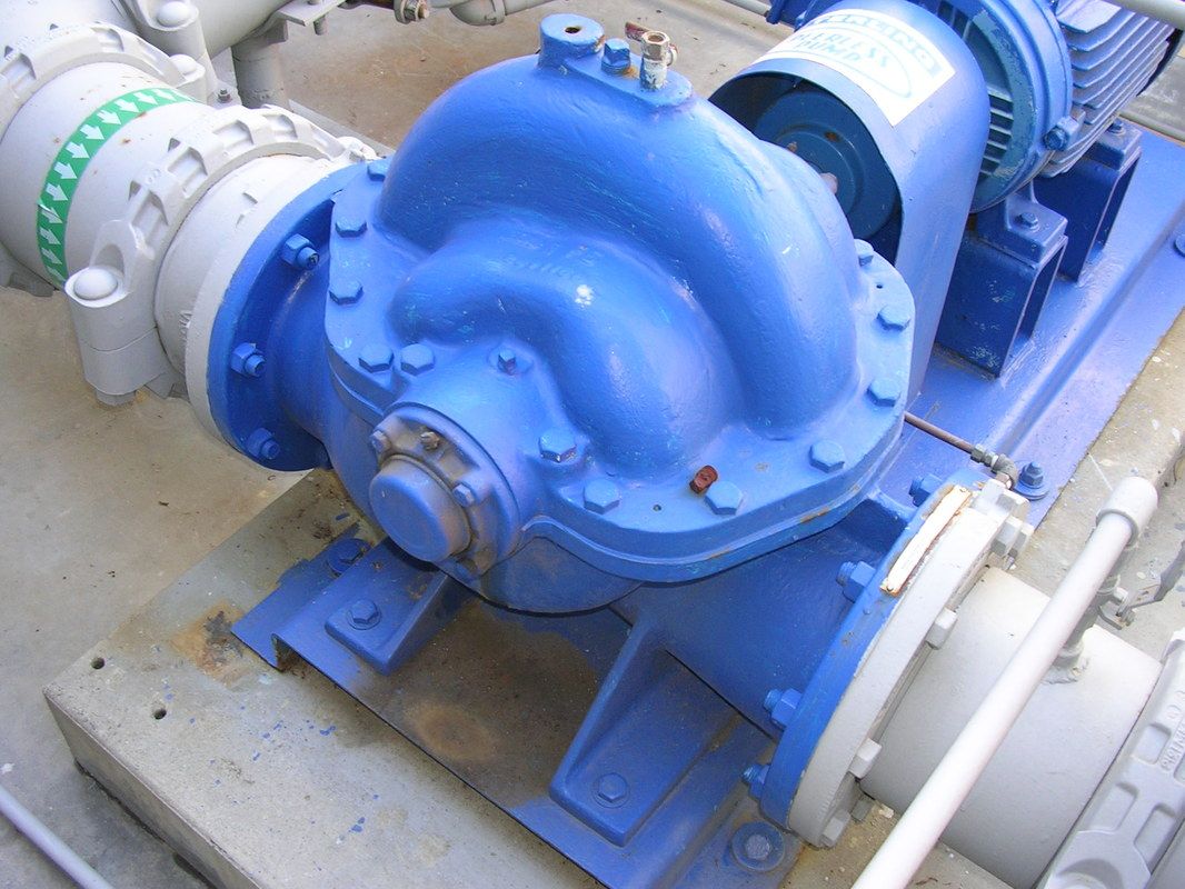
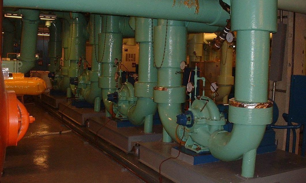
Double Suction PumpThe pump in the three pictures to the left is a double suction pump. It is also a horizontal split case pump, which is described in greater detail in a different part of the gallery.
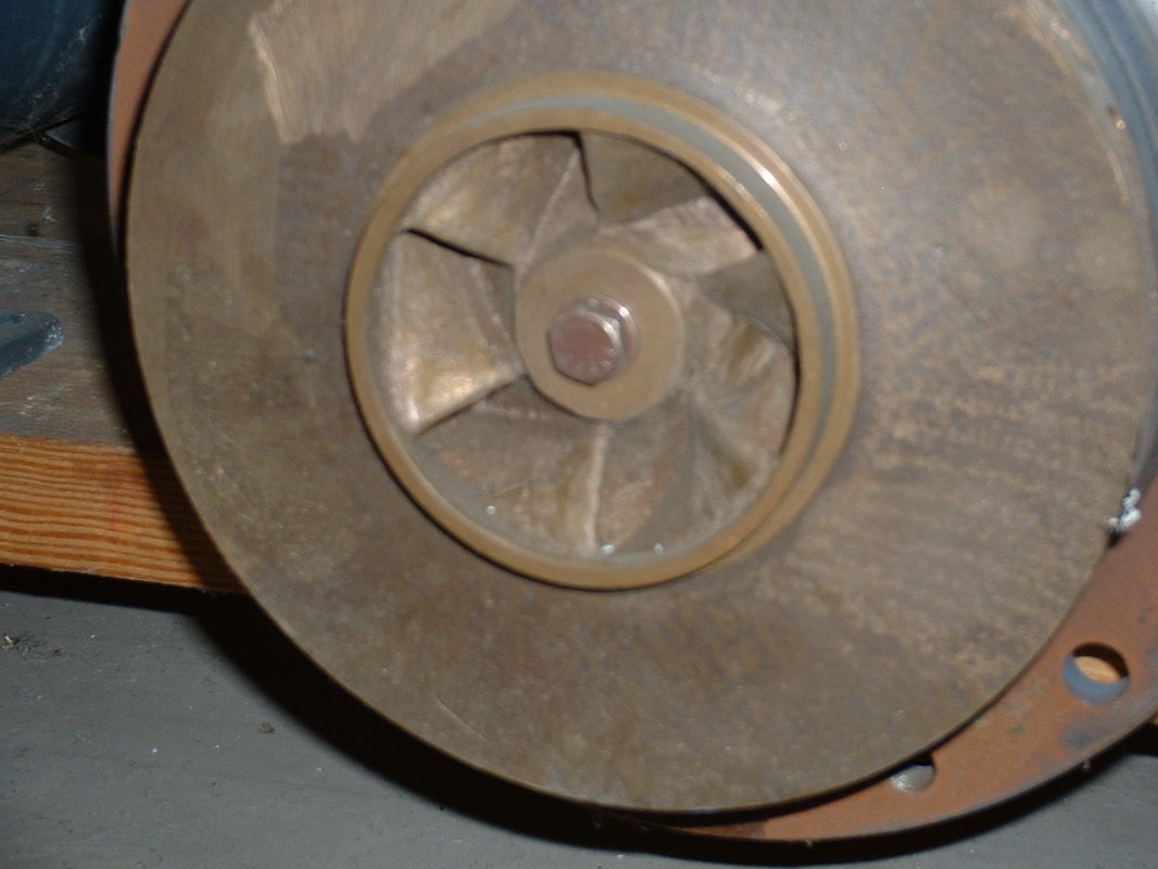
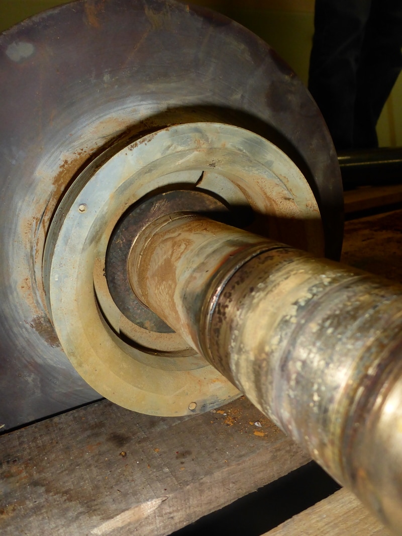
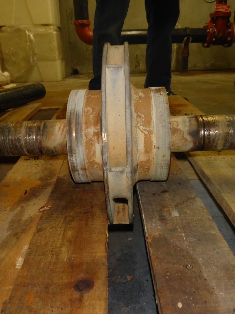
If you look closely at the inlet connection, which is the pipe towards the bottom of the picture in the first photo and the pipe to the left in the other two photos, you will notice that the pump casting connected to the inlet pump (the blue part; the gray part is the pipe) splits and expands to the full width of the pump body. In this pump, the impeller is inside the large round part in the center of the casting. The two small pictures below will give you a sense of what a double suction pump impeller looks like. Water flows into the hole in the center (left photo - there is one just like it on the back of the impeller) and then, because the disc is spinning, it is thrown to the perimeter by centripetal force and exits the impeller (right photo).
Double Suction Pump Impeller
|
|
Horizontal Split Case PumpThe pictures to the left and below are additional examples of horizontal split case pumps, a type of pump that is also illustrated in the photos above under double suction pumps. The term "horizontal split case" comes from the fact that the"parting surface" - the place where the pump casing comes apart - is in the horizontal plane. In other words,, these pumps are disassembled by removing the bolts in the horizontal flange in the casing and taking the top off. In contrast, vertical split case pumps have their parting surface in the vertical plane, as illustrated in the next section.
|
|
Vertical Split Case PumpThe term "vertical split case" comes from the fact that these pumps are dissembled at "parting surfaces" in the vertical plane. In other words, to service these pumps, you would remove the bolts in vertical circular flanges on the front and back of the casing and removing the front or back of the casing.
|
|
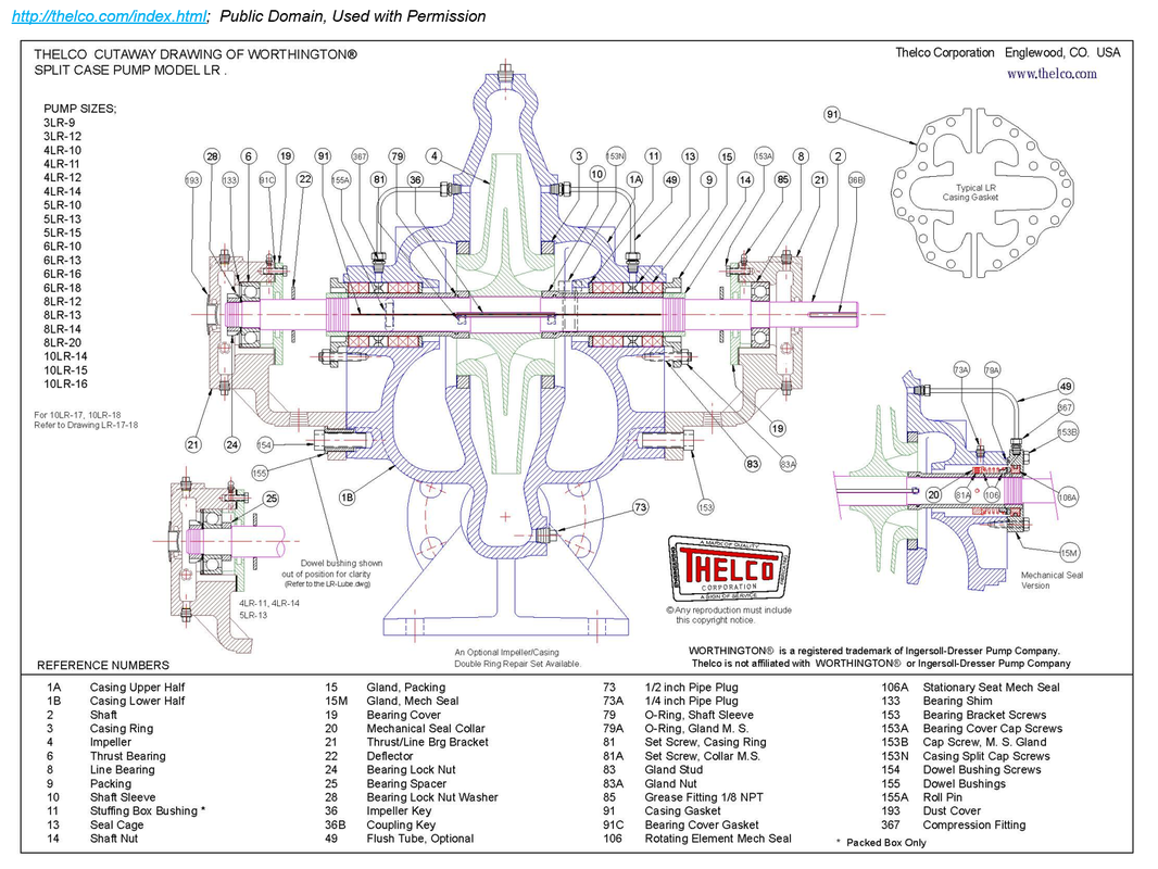
Inside PumpsThese images illustrate what the different types of pumps look like inside. The image below is a cut-away of an end suction pump along with a suction diffuser.
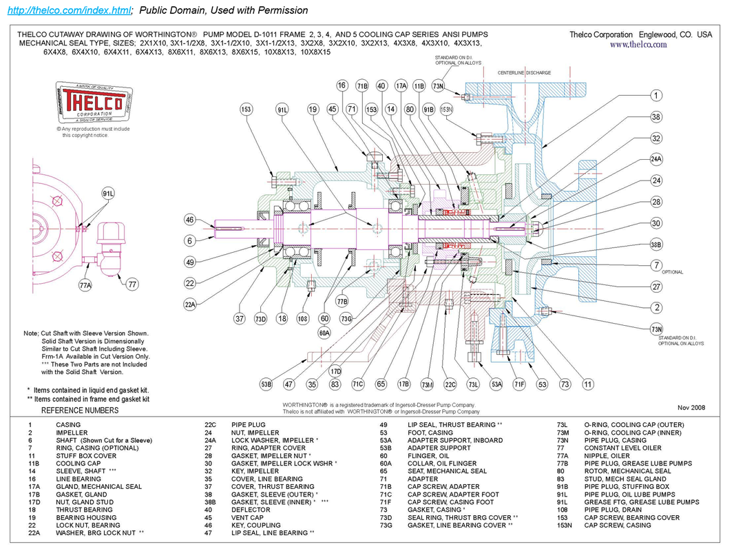
The top picture to the right is a cross-section of an end suction pump with a packing type seal. The second picture is an end suction pump with a mechanical seal. The third picture is a double suction pump with a packing seal but also includes an inset that illustrates what a mechanical seal would look like in a double suction pump. Mechanical seals are the most common in pumps serving HVAC systems. But you often will find a packing type seal in fire protection pumps. That is because mechanical seals will tend to fail catastrophically while packing type seals will show in increase in leakage as they fail but will continue to function, a desirable feature for a piece of equipment associated with fire protection. The down side to packing type seals is that a modest amount of leakage is required to provided lubrication and cooling; typically 10 to 15 drips per minute per inch of shaft diameter. Mechanical seals typically exhibit no leakage when they are operating normally. 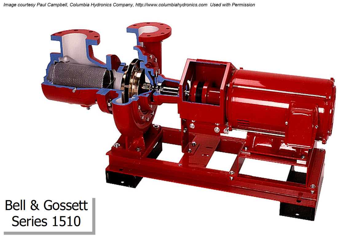
|
|
Inline PumpsUnder Construction
|
|
Vertical Turbine PumpsUnder Construction
|

|
Booster PumpsUnder Construction
|