System Diagram Symbols
|
System diagrams are important design and diagnostic tools, making them useful "across the boards" for the building or system's life cycle. As a project engineer, I was not allowed to go into production until I had a system diagram developed for my system, which had to include first pass equipment selections.
I soon learned that if I got that right, the project would flow really smoothly and a good designer could take my system diagram and lay it out as a real system with-in the physical constraints imposed by the building arrangement and all I would need to do was check it. On the field side of things, I learned early on that a field verified system diagram was worth it's weight in gold; in fact my very first assignment when I came to work for McClure Engineering back on April 16, 1976 was to make a system diagram. I describe that event in a blog post that is the first in a series that will walk you through what a system diagram is and how to make one. And the concept is a key point of emphasis in most of the training classes I am involved with. Over the years, I have come to realize that the major stumbling block for a lot of people who want to be involved in the industry but may not have a design background is coming up with a way to draw a system diagram. When I first started, we did that with a pencil and paper or mylar. |
But, I would not be surprised if a significant percentage of the people doing design currently have never worked on mylar because the industry started moving to CAD (Computer Automated Drafting) in the early 1980's, which generally is a good thing. But having CAD proficiency can be time consuming and having a CAD drafting package can be expensive. Plus, there is a pretty steep learning curve associated with CAD.
For instance, in my very first encounter with a CAD system (called CAD Medusa), I spent a day trying to figure out how to draw a line and save it. At some point in there, I crashed the computer system as I floundered around trying to figure the software out, which turned out to be a big problem because that same system was the one accounting used and they were getting ready to run payroll.
In contrast, a lot of people these days are somewhat comfortable with Microsoft Office products (which can also have a learning curve I realize) (and comfortable could be a relative term I realize). Personally, I use PowerPoint a lot and I have come to realize that once you spend some time figuring things out, you can draw some pretty good stuff with the basic drawing tools it contains. So, while my first choice for doing a system diagram in terms of utility and features would be AutoCAD, my first choice for someone just learning to do system diagrams who I was hoping would embrace the concept would be PowerPoint.
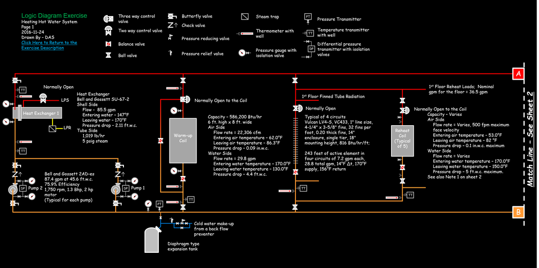
Towards that end, I started drawing system diagrams for my classes in PowerPoint. And as a result, I have a file with a bunch of symbols in it that is constantly growing. The system diagram symbols are created using Microsoft Office drawing objects. If you are not up to speed on how to work with those, it is not particularly difficult and you will find links to a number of tutorials about the basics on the Logic Diagram Tool page since that tool also uses MS Office drawing objects.
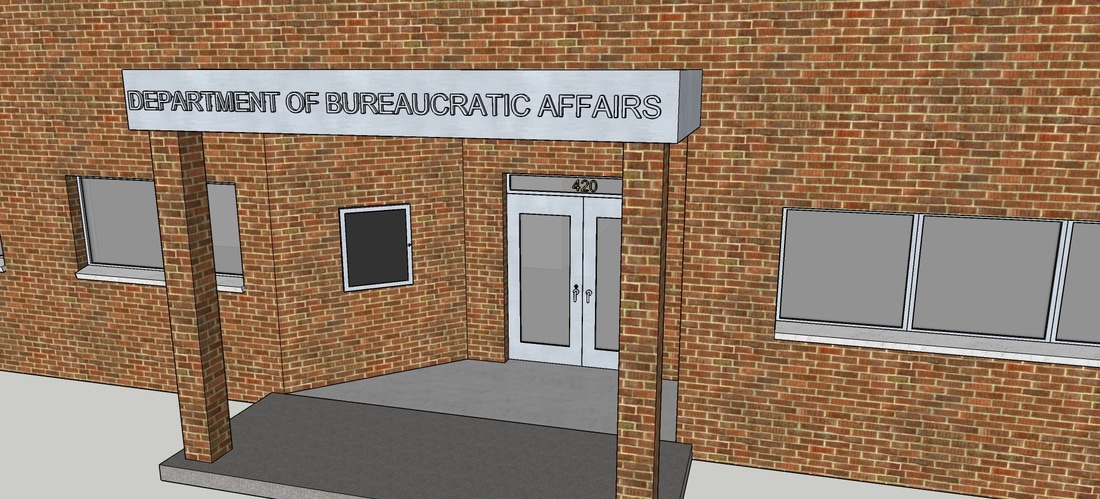
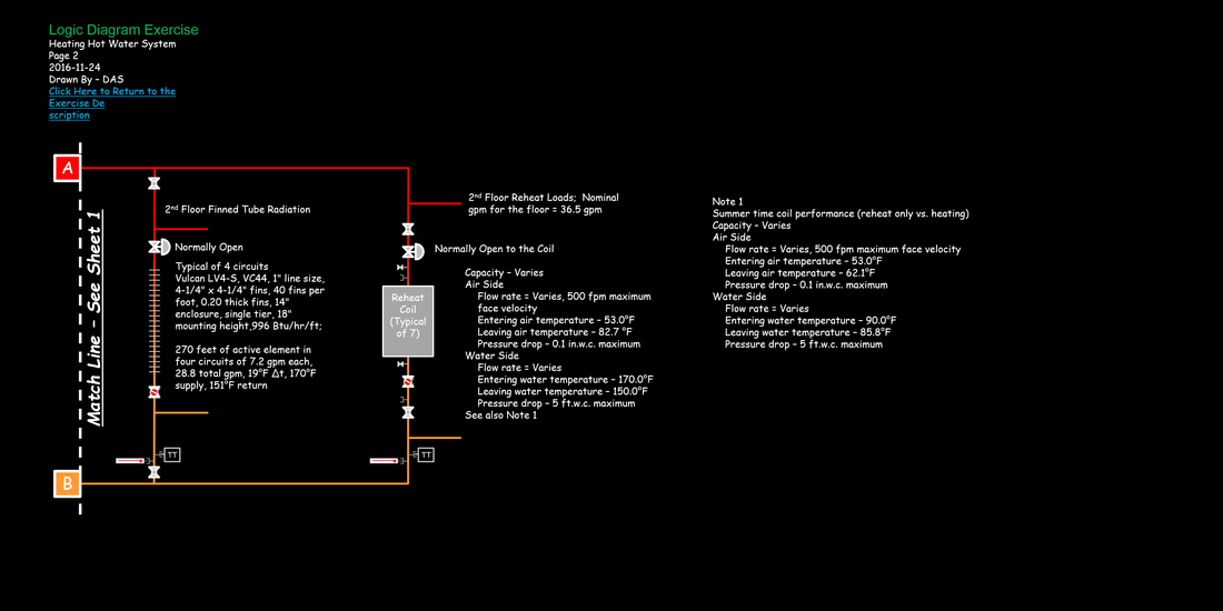
You may also find a couple of the GoToMeeting sessions I recorded with students to help them develop their system diagrams to be useful. In them, we discuss system diagram techniques, calculation techniques for savings estimates based on some of the opportunities they identified via their system diagram, and how to work with MS Office drawing objects in the first place. All of the students offered to share the meetings in case the information would be helpful to others, so hats off to them for their willingness to do that.So my bottom line here is that the link above that takes you to the blog post describing my first system diagram experience will hook you up with a string of posts providing instructions for developing a system diagram. The links below will take you to a copy of my current PowerPoint symbols library and a copy of the Department of Bureaucratic Affairs building hot water system diagram. There is also a system diagram for the air handling equipment serving a hotel lobby and adjacent meeting space to give you an example to work from for an air system. All of this is in the hope that this will facilitate the development of system diagrams by those who are not AutoCAD users.
For those who are AutoCAD users, I have also included a download link that has my current AutoCAD system diagram symbol set along with sample air and water system diagrams developed in AutoCAD.
I offer all of these at face value, meaning I am happy to facilitate your system diagram development process, but you need to be responsible for how you use them and for figuring out what everything is. The AutoCAD collection in particular has elements in it from back when you could only have 8 letters in a file name, so they are pretty cryptic. If that makes you crazy, then by all means, just create your own symbol.
I plan to update the symbols files occasionally, so check back if you find what is here useful. You will be able to see if I have added to it by checking the What's New link on the home page and searching the page it takes you for the words "System Diagram".
Finally, I should mention that the Student Union Air System Diagram is the system that is used by the Functional Testing Guide in a chapter it has that is takes a look at the role commissioning and functional testing played and some of the challenges encountered when the system serving the imaginary student union was built and brought online; its sort of a nerdy commissioning novel.
| 2017-06-30 Power Point System Diagram Symbols (symbols_-_black_vweb1.pptx) |
| PowerPoint Department of Bureaucratic Affairs Building Hot Water System Diagram (bureaucracy_building_system_hw_diagram.pptx) |
| PowerPoint Hotel Lobby Air Handling System (hotel_lobby_ahu_system.pptx) |
| 2017-06-30 AutoCAD System Diagram Symbols (simple_flow_diagram_symbols.zip) |
| AutoCAD Condenser Water System Diagram (sample_water_system_diagram.dwg) |
| AutoCAD Student Union Air System Diagram (sample_air_system_diagram_v2_r1.dwg) |


