Chilled Water Plant System Diagram Exercise
This is an updated version of an exercise I originally published on the blog back in September of 2013. I posted it to provide an on-line version of an exercise I had done in class, which was the first time I had tried using a SketchUp model as a teaching aid. It was very well received and since that time, I have been using models more and more in the classes to provide a virtual field experience.
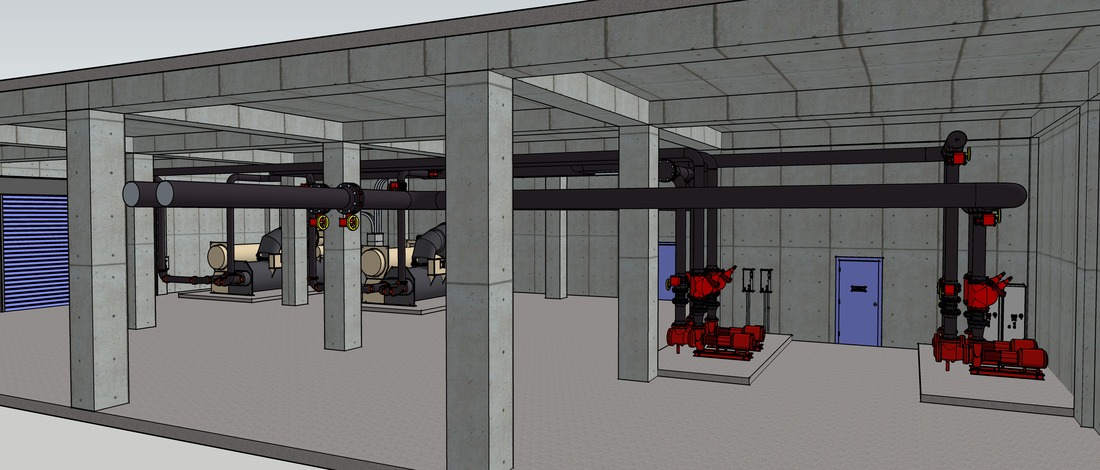
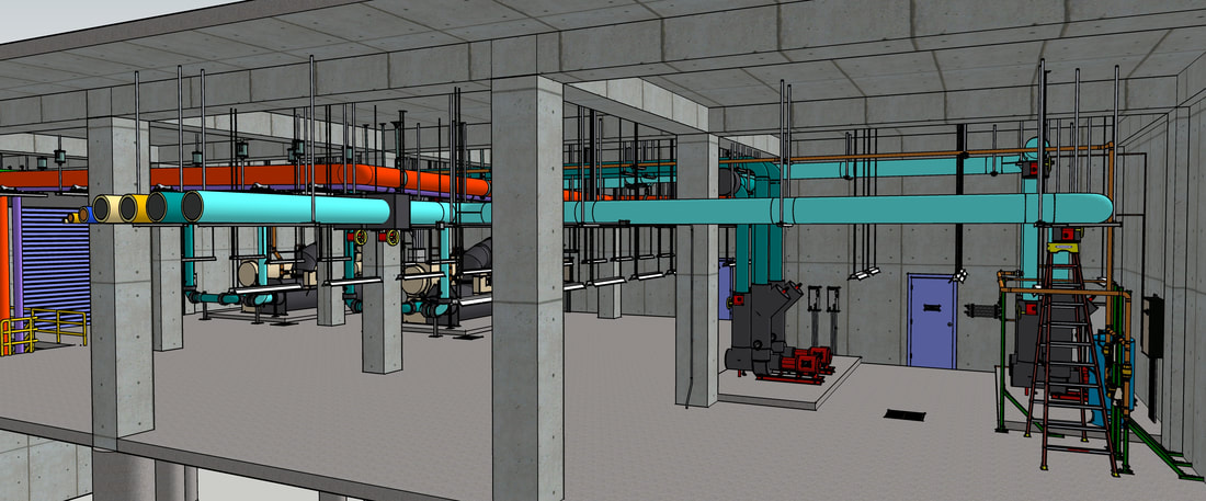
In the case of this particular model, the goal of the exercise is still the same, that is, the goal is to work your way through the model to develop a system diagram for the chilled water side of the plant. But what has changed since 2013 is the level of detail in the model, as you can probably tell if you contrast the two images below; the left image is the model as it existed for use in the first exercise. The right image is the current version from about the same perspective.
In the case of this particular model, the goal of the exercise is still the same, that is, the goal is to work your way through the model to develop a system diagram for the chilled water side of the plant. But what has changed since 2013 is the level of detail in the model, as you can probably tell if you contrast the two images below; the left image is the model as it existed for use in the first exercise. The right image is the current version from about the same perspective.
|
|
The primary benefit to the newer model in terms of the exercise is that it has more detail and is more complex, just like an actual mechanical room. In other words, the only piping system available in the original model was the system you were focused on for the system diagram. In the current model, other systems, both mechanical and electrical have been layered in; things probably will not be as obvious and things will be in the way of what you are trying to see. Having said that, a real mechanical room will be even more complicated and potentially intimidating.
For instance, so far, I have not figured out how to make the light fixtures have glare that almost perfectly obscures what you are trying to see from the ground below them. And so far, no virtual dirt.
I think you will also find the virtual ladder you have at your disposal by virtue of being able to zoom, pan, and orbit around in the model is much easier to use than a 14 foot stepladder, especially the 14 foot wooden step ladders that were the rule back before fiberglass ladders made their way into the industry. And if a bird's eye view would help you understand something, you can simply turn off the drawing layer that holds the floor above. Try that in a real mechanical room.
So bottom line, the hope is that the model will give you a way to ease into the field side of developing a system diagram, but there still will be some new things to experience when you try this out in an actual facility. But hopefully, having done the field work once in a virtual environment, you will find your self a bit less overwhelmed by what you will encounter out in the field.
|
| ||||
To help make it easier to navigate, the file is set up with "Scenes", which are basically saved camera locations that will put you in a certain area in the model with out having to do quite so much zooming, panning, and orbiting. In addition, certain layers in the scene have been turned off to facilitate your exploration. For instance, in one of the scenes has the roof and beams above the plant turned off, allowing you to move and pan around for a "birds-eye" view of things.
The scenes are numbered and to facilitate your ability to work with them, we created a Scene Guide, which you can download using the link above and then reference for general information on working with scenes as well as specific information and a thumbnail image of each scene in the model.
If you want to see what the cooling towers for the plant look like, you will find that model under the Cooling Tower Scoping Exercise page. Similarly, if you want to see what one of the air handling units served by the plant looks like, then that model is included under the Ballroom AHU Scoping Exercise page.
|
I have yet to develop new video that shows the answer to the exercise and discusses how the plant works using the latest version of the model. But the videos referenced below will give you a general idea of that. Meanwhile, the file to the left is the "answer" in the form of a system diagram I made using PowerPoint.
| ||
|
|
The video to the left sets up the exercise and also gets you up to speed on how to do basic navigation in SketchUp. I made it using an older version of the chiller plant model than the current version, but the current versions just adds more detail. So while the images you see in the video may look slightly different from what you see in the current model, the guidance and concepts all still apply. |
Under Construction
|
This is a place holder for a video and files that will provide the answer to the exercise. I am still working on putting the video together but expect to have it available by the end of the last week of October if not sooner.
Until then, you can still view the video that I made for the original version of the exercise by visiting the post titled System Diagrams: Practice Making a System Diagram –The Answer on the blog. The plant in the current model has much more detail than the model used for the answer in the blog post. But the general configuration is the same, thus the system diagram is the same. And the operating theory I discuss and related resources all still apply. |