Economizer Stratification
The information on this page complements a blog post I did titled Retrocommissioning Findings: Economizer Mixed Air Plenum Stratification–Overview.
A while back, I had the opportunity to work with Brian Clark, Jay Tulley, and Ryan Stroupe on an economizer equipped air handling system serving a dental clinic in Monterey, California. So what follows represents the combined effort of all of us and I wanted to acknowledge that.
A while back, I had the opportunity to work with Brian Clark, Jay Tulley, and Ryan Stroupe on an economizer equipped air handling system serving a dental clinic in Monterey, California. So what follows represents the combined effort of all of us and I wanted to acknowledge that.
|
|
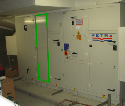
The image to the left is the air handling unit we were working on. The supply fan is in the last section to the right and the area highlighted with the green outline is the location of the cooling coil. The filters and mixed air plenum are located to the immediate left of that location in the air handling unit casing.
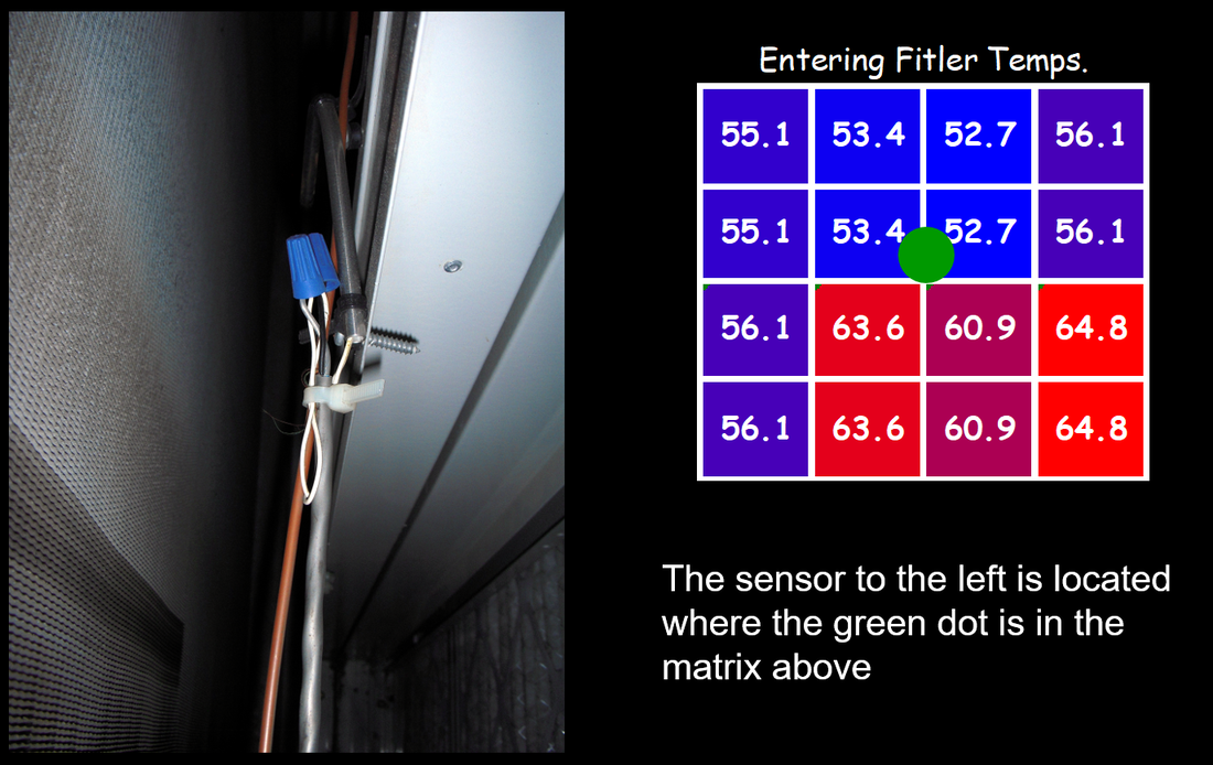
The image to the right is the temperature sensor that was controlling the economizer. It was not an averaging sensor and only measured the temperature at the tip of its sensing element, which was located where the green dot is on the matrix to the right of the picture. The matrix is simply a grid created based on the filters in the unit; i.e. each square is a filter. The numbers in the square represent the temperature we measured in the center of each filter under one operating condition. As you can see, the single point sensor likely was not doing a good job of measuring the true mixed air temperature in the plenum.
In addition to the temperature stratification that existed in the unit when the economizer was active, there was significant velocity stratification in all operating modes due to the configuration of the outdoor air and return air ducts and dampers where they connected to the back of the AHU, which is illustrated in the image below.
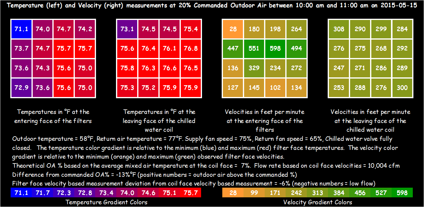
At the time Ryan took the velocity readings depicted in the two carpet plots to the right, the unit was locked on 20% outdoor air, so the temperature stratification (the carpet plots on the left) was not as severe as it was in the previous image, which was associated with a point in time when the economizer was active. But even on minimum outdoor air, with 58°F outdoor air, there was over 5°F of temperature stratification across the mixed air plenum.
The pairs of carpet plots in the image above represent the conditions entering and leaving the cooling coil at the time of the test. For the two blue to red gradient plots, the far left plot is the temperature gradient in the mixed air plenum ahead of the cooling coil and the blue to red carpet plot to the right of it represents the temperature gradient leaving the cooling coil at the same point in time at the same location on the grid. Note how the mass of the coil and the water it contains has an impact on the stratification pattern, smoothing it out a bit. For reference, the coil was not active at the time; i.e. there was no water flow through it.
Similarly, if you study the two gold to green velocity carpet plots on the right side of the image, you can see that the coil does a very good job of eliminating the velocity stratification because the resistance to flow created by the coil causes the air to want to distribute itself uniformly. That implies that if you are planning to traverse the cross section of an air handling unit to determine a flow rate, you will get better data if you are down stream of a coil vs. what you would likely encounter if you made the traverse in the mixed air plenum.
The velocity measurements above were manual measurements so we only have that data for one point in time. But the temperature measurements were taken with data loggers that were deployed in an array across the entering and leaving face of the coil. The result was the time series that is illustrated below.
Note that we did a relative calibration of the sensors prior to deploying the loggers so we could eliminate sensor error as a reason for a temperature difference. You can find additional information on relative calibration in the Functional Testing Guide. There is a link to it in Appendix D; the test ID is 1005. You will find test guidance in the section on Integrated Operation and Control.
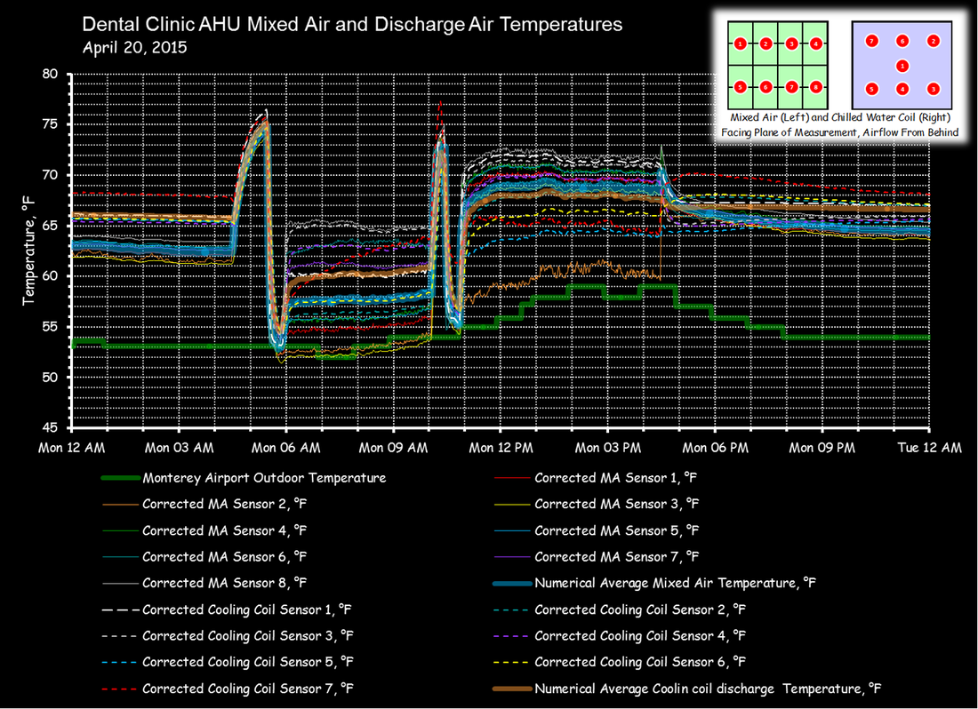
As you can see, the patterns in the plenum change significantly as the unit goes through an operating cycle. More specifically, the spike around 4:30 AM is associated with the unit starting up and going into a warm-up cycle for a while. Then, around 5:30 AM, it goes to minimum outdoor air and then starts to operate in an economizer cycle. Between 10:00 AM and 11:00 AM, the system transitions back to minimum outdoor air but then returns to the economizer cycle.
Since the outdoor air is warming up, the damper positions are changing, which causes the stratification patterns to change over the course of the day.
Finally, at 4:30 PM, the system shuts down, causing the temperatures to start to converge. But damper leakage still influences the sensors in the array and the plenum never fully stabilizes at one temperature.
The carpet plots were created in a spreadsheet I built that allowed me to pick a point in time and see what the pattern looked like. While sharing this with Brian and Jay, I lamented the fact that I did not know enough about Visual Basic to automate the process so you could watch the carpet plot change automatically as the selected data points varied over time. Jay offered to take that on and the result is the following very cool video.
Finally, you will find additional information about air side economizers on the Pacific Energy Center Classes page of the website where the materials for the most recent version of the day-long air-side economizer class Ryan occasionally offers there are located.