A Field Perspective on Engineering Commissioning Resources
  • Home
    • What's New
  • Blog
    • Blog Support
  • SketchUp Models
    • SketchUp Resources
    • Bureaucratic Affairs Building HHW System Logic Exercise
    • Bureaucratic Affairs Building Scavenger Hunt
    • Chilled Water Plant System Diagram Exercise
    • The HIjend Hotel >
      • Chilled Water Plant Scoping Exercise
      • Ballroom AHU Scoping Exercise
      • Cooling Tower Scoping Exercise
  • Tools
    • Altitude Correction Factor
    • Economizer Evaluation Checklist
    • Eikon for Educators and WindLGC
    • Effective Duct Length Tool
    • Excel Third Axis Tool
    • Excel Time Value Conversion
    • Insulation Savings Tools
    • Logic Diagram Tool >
      • Logic Diagram Example - Discharge Air
      • Logic Diagram Example - CHW Plant 01
      • Logic Diagram Example - VAV AHU
    • Mixed Air Calculations
    • Monitoring Plan Spreadsheet
    • Pipe Friction Chart
    • Plot Digitizer >
      • Plot Digitizer Pump Curve Example
    • Square Law Spreadsheet
    • System Diagram Symbols
    • Thermodynamic Diagrams Spreadsheet
    • Universal Translator Data Analysis Tool
    • y = (m * x) + b Spreadsheet
  • Useful Formulas
    • Affinity Laws
    • Circular Equivalent Duct
    • Effective Duct Length
    • FT Guide Appendix C
    • HVAC Equations and Concepts
    • Hydraulic Diameter
    • Pump Power and Energy
    • "Square Law"
  • What's That Thing?
    • Cooling Towers
    • Pumps
    • Valves
  • Resources
    • Bill Coad's Writings
    • Data Logging Resources
    • EBCx Skills Guidebook
    • Energy Design Resources
    • Fisher Controls Valve Cavitation Bulletin
    • Functional Testing Guide
    • Honeywell Gray Manual
    • MCC Powers Bulletins
    • NBCIP Reports
    • PEC Tool Lending Library
    • PID Resources
    • Pneumatic Control Resources
    • Resource List
    • Scoping Resources
    • TAB Resources
    • Vintage Carrier Design Manual
    • VRF Systems
    • Williams' Wisdom
  • Videos
    • Bureaucratic Affairs HHW Logic Answers
    • Cooling Tower Flow Variation
    • Economizer Stratification
    • Functional Testing
    • Induction Principles
    • Monitoring Plans
    • CW Pump Deadheaded by Tower Lift
    • Ripple Effects
    • Testing a Pump
    • The Garden of Low Entropy
    • Variable Flow Systems
  • Training
    • Materials from Classes and Presentations >
      • ACEEE
      • ASHRAE
      • ASHRAE - Engineers Notebook
      • BCxA and NCBC
      • BEST Institute
      • Case Studies
      • ERDC 2020 RCx Academy
      • ELPNW
      • ICEBO
      • Marriott AEP
      • Magazine Articles
      • NAVFAC
      • Pacific Energy Center Design, Performance and Commissioning Issues Classes
      • Pacific Energy Center EBCx Project Review
      • Pacific Energy Center EBCx Workshop Series >
        • EBCx Workshop Series 12
        • EBCx Workshop Series 13
        • EBCx Workshop Series 14
        • EBCx Workshop Series 15 >
          • Student One On One Discussions
        • EBCx Workshop Series 16
        • EBCx Workshop Series 17
        • EBCx Workshop Series 18
      • Portland General Electric
      • U of W >
        • U of W Archive
    • On Demand Training >
      • Benchmarking UCA and Scoping
      • Loads and Psychrometrics
      • Induction Motor Principles
      • Introduction to Functional Testing
      • Scope of Work Documents
      • System Diagraming
    • Training Opportunities
  • Contact
    • Copyright and Permissions

Valves

Valves are the gate keepers in our piping systems, controlling the flow through them in a number of ways.  While some of the ones you may encounter out in the field may be totally unfamiliar to you, most of us use valves every day at home.  For example, the faucet on your kitchen sink is a type of valve.

There are many, many different types of valves, classified primarily by their physical features (gate valve, check valve, etc.) and/or their function (service valve, check valve, etc.).  As a result, the gallery in this section of the website is subdivided by those classifications to organize it a bit more.
​

To use the gallery, scroll down until you find something that looks like what you saw out in the field.  If you don't find what you are looking for, feel free to submit a picture of what you saw and we will see if one of the folks on our team can identify it and then add it to the appropriate gallery if it is something new.
 
Use the navigation tabs at the top of the page to get back to the home page or a different part of the web site.
Picture
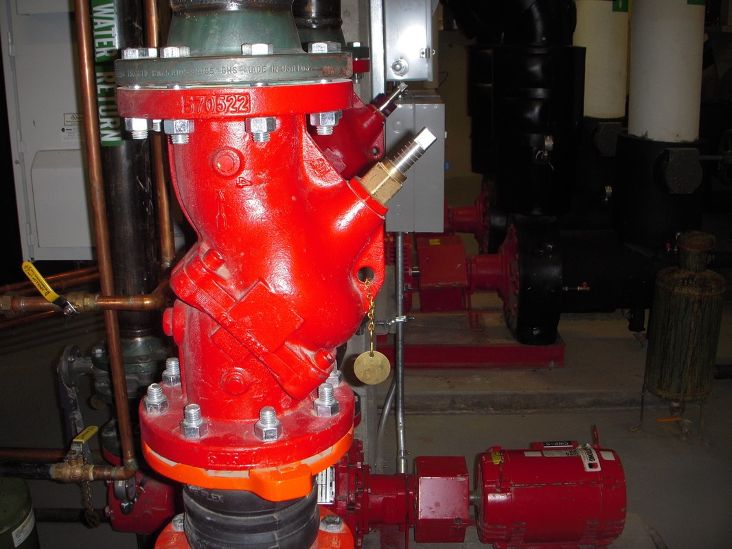
A Combination Service Valve, Check Valve and Throttling Valve
Picture
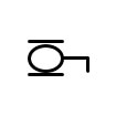
A Common Drawing Symbol for a Combination Valve

Service Valves

Service valves are used to isolate equipment or other valve types from the system that they serve so that repairs can be made or maintenance performed.  For instance, a chiller will usually have service valves on its inlet and outlet connections so you can isolate the various tube bundles from the piping system to clean the tubes with out having to drain the entire system.
 
In the picture to the right, the bronze colored pressure regulating/pressure reducing valves have gate valves on each side of them to allow the pressure reducing/regulating valves to be isolated from the system for service and repair.
 
Service valves are intended to be either fully open or fully closed and are not intended to regulate flow.   In fact if you try to regulate flow with some types of service valves, like a gate valve for instance, you will eventually damage the valve seat and it will no longer be able to provide the desired isolation function.

In contrast, most flow regulating valves can also act as service valves if they are completely closed, all though some of them might not be rated "bubble tight" and thus, would exhibit a minor amount of leakage if being used as a service valves (generally drips, not a stream of water).
Picture
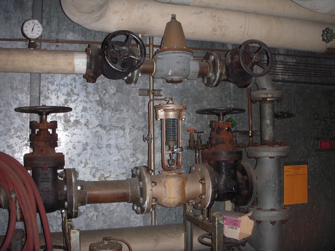
Gate Valves (theBlack Items) Being Used as Service Valves for Pressure Reducing/Pressure Regulating Valves (Bronze and Bronze/Gray Colored Items)
Picture
Picture
Picture
Drawing systems for Common Service Valves;  A Gate Valve (Left), a Butterfly Valve (Middle) and a Ball Valve (Right)
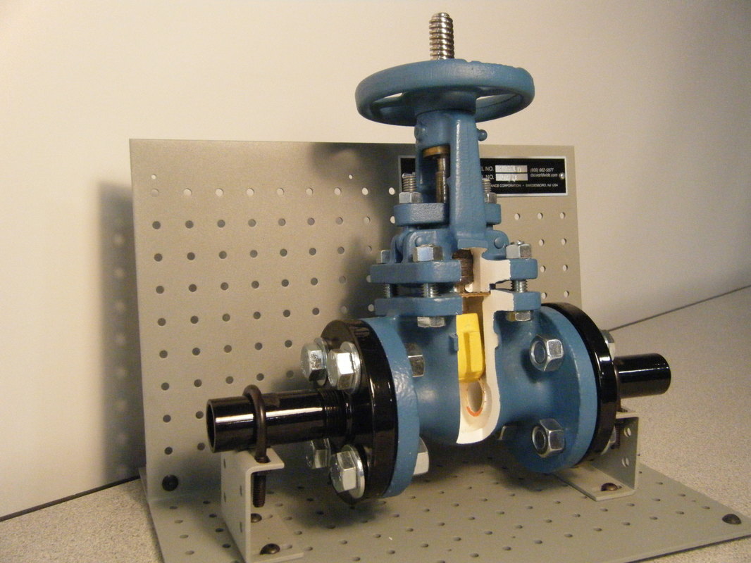
Picture
Picture
Picture
Picture
Picture

Gate Valves

The picture to the right a gate valve that has been cut-away to reveal its internal parts.  I should mention this picture and the other cut-away valve pictures on this page were taken using training samples generously provided by Ryan Stroupe of the Pacific Energy Center.

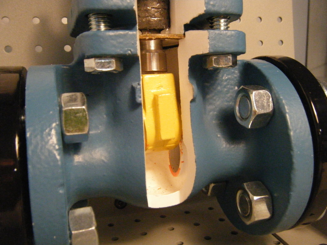
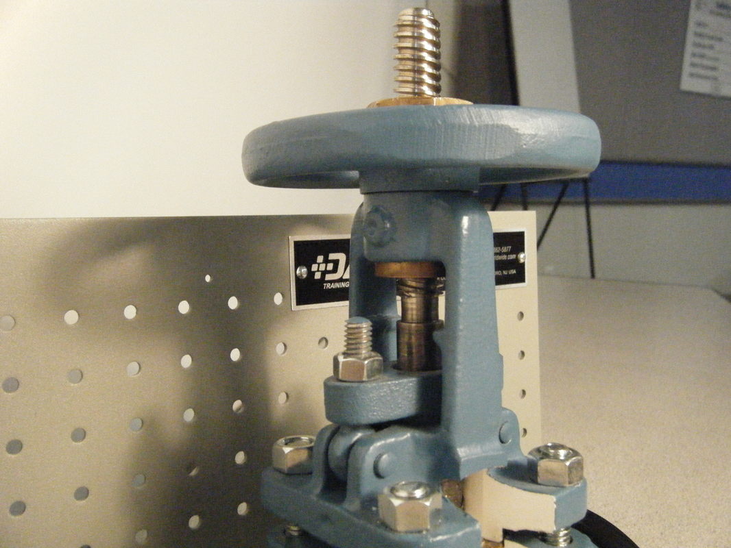
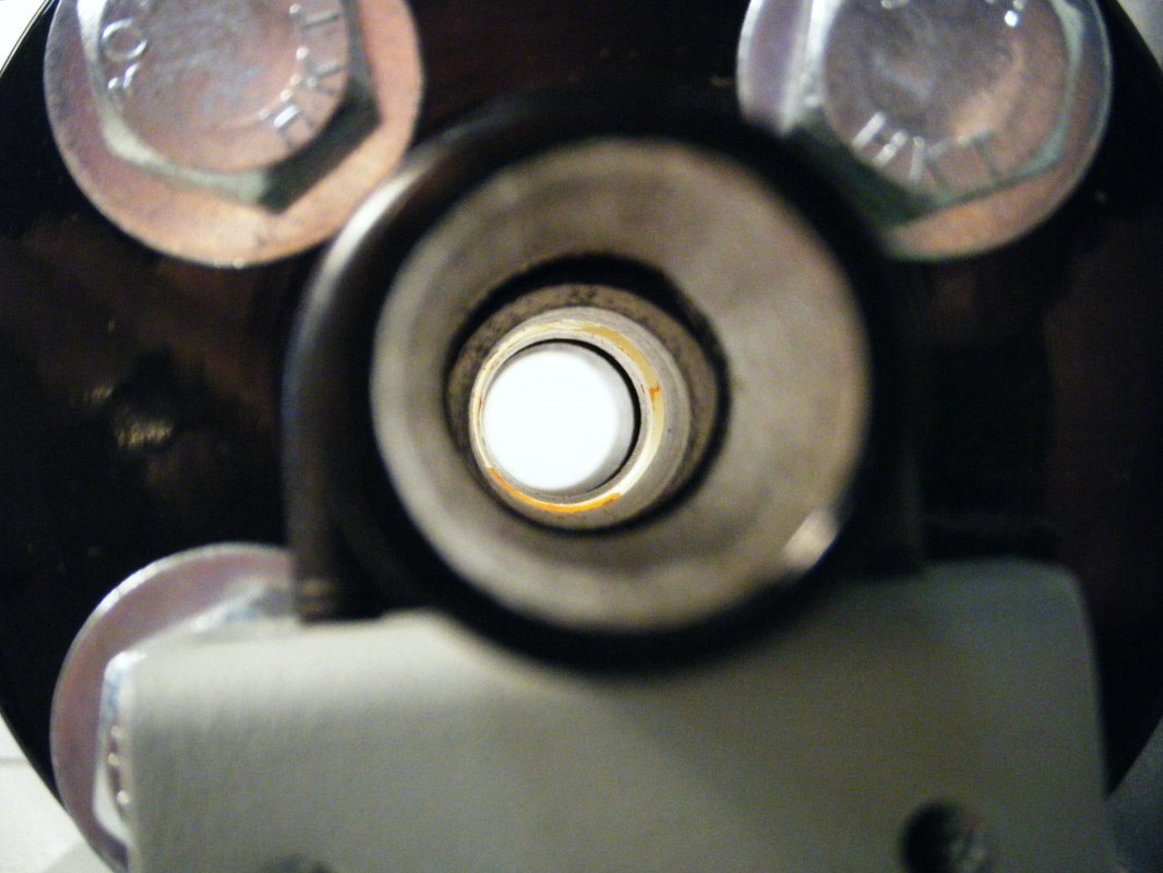
As you can see from the close-up pictures that follow, the working mechanism of the valve (the yellow part) is literally a gate that moves up and down as you turn the valve handle.  When the valve is fully open, there is a "clean shot" for the fluid to flow through it with virtually no pressure drop, as can be seen from the left smaller picture below the cut-away.  As you close the valve, the gate moves across the opening in the valve, as you can see from the right smaller picture, until the passage is completely closed off.

Gate valves are only intended to operate fully open or fully closed.  If you try to use one only partially open to regulate flow, the high velocities generated by the flow passing under the partially opened gate will erode it.  When that happens, the valve will no longer close and becomes somewhat useless in terms of isolating equipment.

This particular valve is called a rising stem valve because as you open it, the valve stem literally rises up out of the valve hand-wheel.   This can be a desirable feature because it gives you a positive indication that the valve is actually open (assuming the gate has not come of the stem, which has been known to happen).  

Because of this, fire protection systems make frequent use of this type of valve and will typically have a switch monitoring the valve stem so a trouble alarm can be generated if the valve is in the wrong position, potentially compromising the ability of the system to suppress a fire where one to occur.  If you look closely at some of the pictures of the fire pumps in the "Pumps" section, you can see the switches and the extended stems on the open valves.

Note that there are also gate valve designs where the stem does not rise as you open the valve,  Rather, the gate rides up the stem as you turn the valve wheel.

This particular type of valve is also called and overhead steam and yoke valve (often abbreviated OS&Y) due to the design of the mechanism supporting the valve stem and packing.  In the close-up below the two smaller pictures, the horizontal part about one third of the way up the valve stem is the packing gland.  As you tighten the nuts associated with it, the packing gland compresses a seal around the stem which keeps the fluid inside the valve from leaking out.  

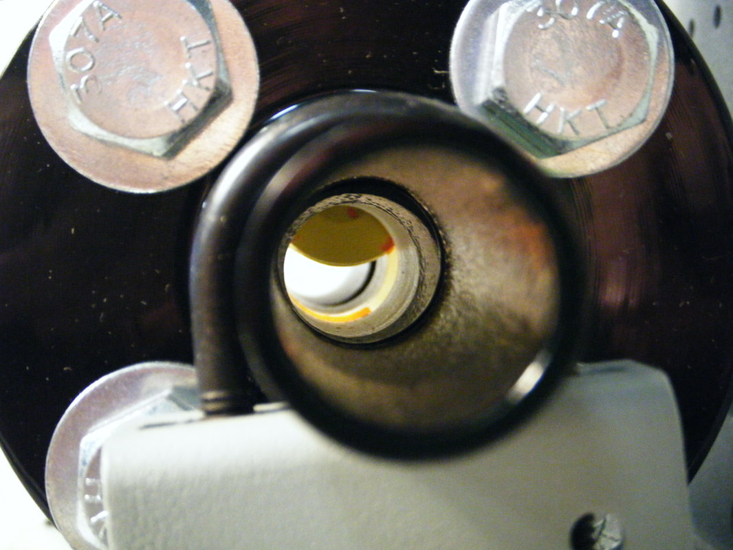
The video clip above illustrates what happens as you open and close a rising stem gate valve.  The other images below are examples of gate valves applied out in the field.
Picture
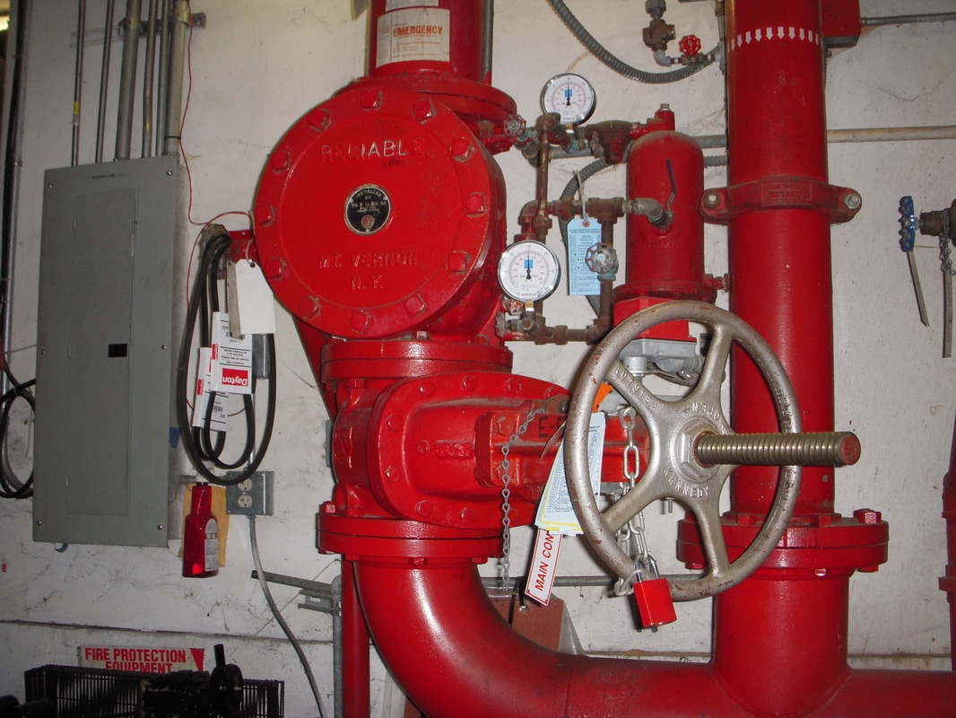
Open Rising Stem Valve with Tamper Switch
Picture
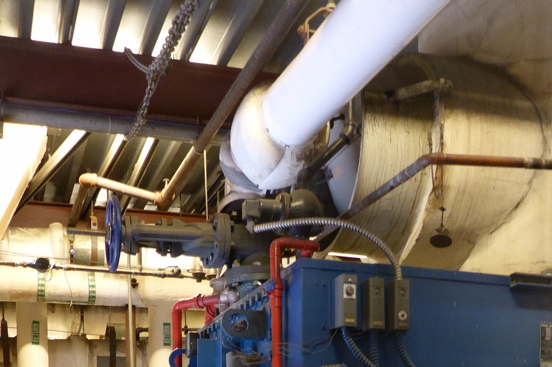
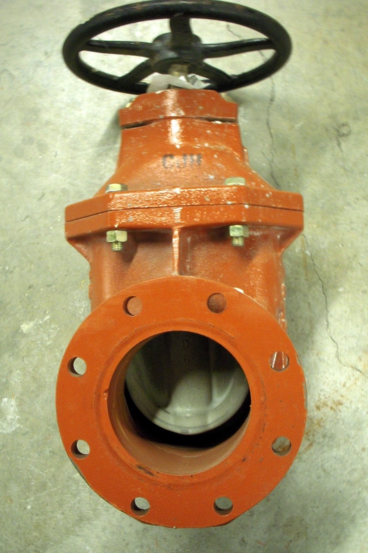
Rising Stem Gate Valve for Isolating a Hot Water Boiler
Picture
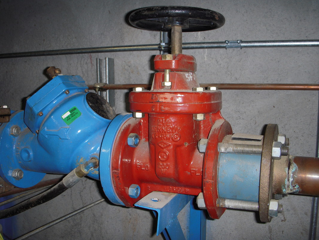
Service Valve for a Reduced Pressure Principle Back Flow Preventer
Picture
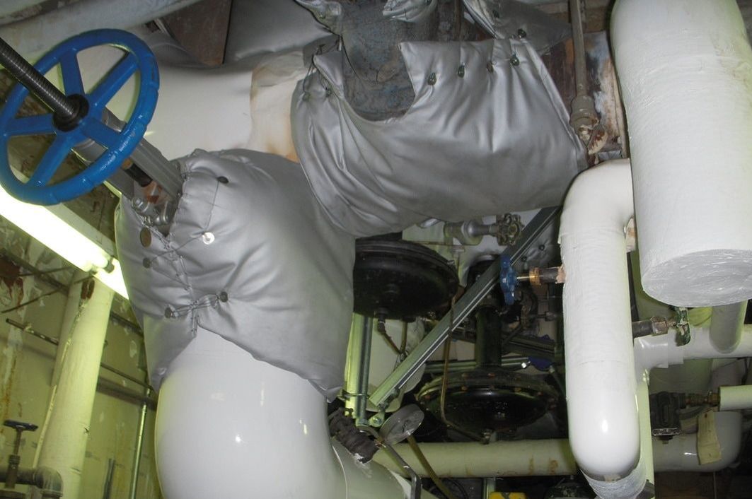
Gate Valves with Removable Insulating Blankets
Picture
Partially Open Gate Valve
Picture

Butterfly Valves

Under Construction

Picture

Ball Valves

Under Construction

Check Valves

Picture

Swing Check Valves

Under Construction

Throttling Valves

Picture

Globe Valves

Under Construction

Combination Valves

Picture

Triple Duty Valves

Under Construction

Control Valves

Picture

Three-way Valves

Under Construction

Pressure Reducing/Regulating Valves

Picture

Steam Pressure Reducing Valve

Under Construction

Pressure Relief Valves

Picture

Refrigerant Pressure Relief Valve

Under Construction

Home

Blog

Contact

Picture
A Field Perspective on Engineering - © 2017 Facility Dynamics Engineering, All Rights Reserved
(Contact Me to Check on Lefts or Any Other Questions You May Have about Permissions)