Hijend Hotel Lobby and Administration AHU Minimum Outdoor Air Percentage Estimate Exercise
The files below are the answer to the exercise using the psych chart to determine the minimum outdoor air percentage for the Lobby and Administration Area AHU in the Hijend Hotel. The answer is illustrated on three different forms of the electronic psych chart. The .pdf files are just that. The .hdd and .aad files are the files that you would use to open the answer in the actual phsych chart software. The data table file is the same for all charts.

|
|
| ||||||||||||
| lobby_and_admin_ahu_answer.xlsx |
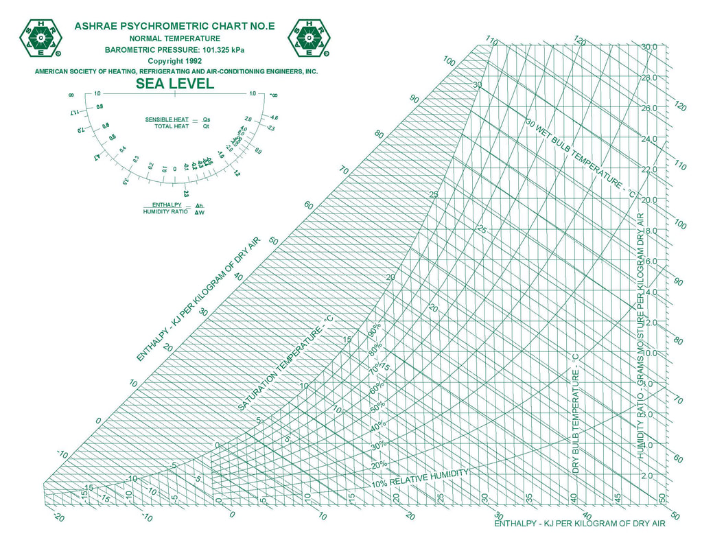
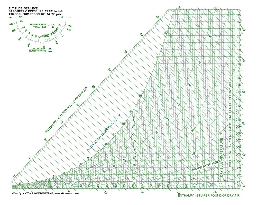
PDF and Image Psych Charts
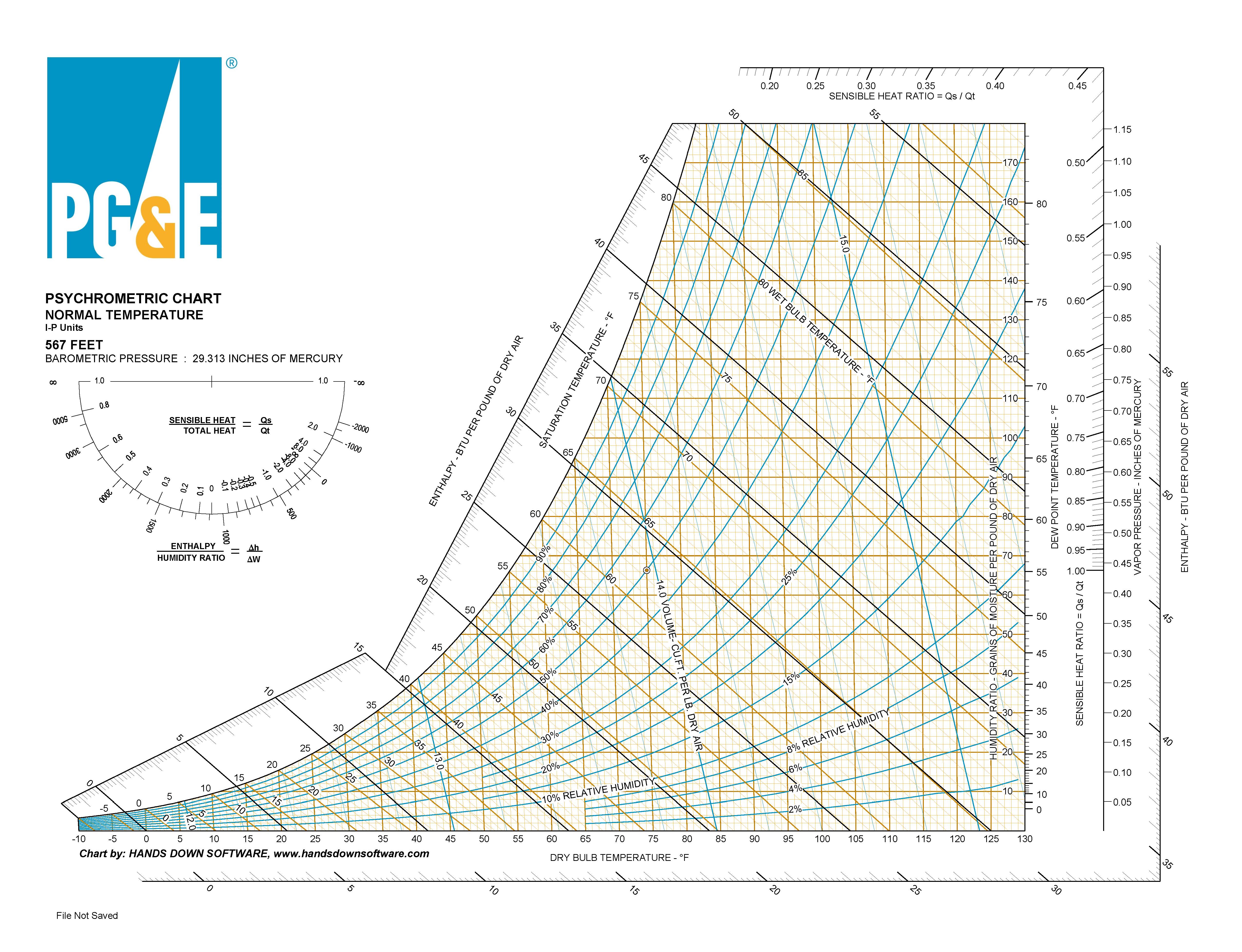
The files below are blank psych charts in a number of different publicly available forms that you can download and use to work with a psych chart manually, either by printing it and actually writing on it (like we did in the olden days) or by inserting it into a PowerPoint or similar application and using the application drawing tools to work on it.

|

|

| ||||||||||||
If you would like to try your hand at an electronic chart, this blog post will give you link to a free one you can use along with guidance on how to use it.
Joseph Olivieri Book Chapters

|
|
The files below are scans from chapters in a book by Jospeh Olivieri titled How to Design Heating Cooling Comfort Systems. The copyright is 1973, and many would say the book is outdated.
And while that is true in some ways, given what we have learned since then, and the many wonderful tools we have, in particular, personal computers and their related software, the principles behind those tools are the same principles discussed in the book. And, thus, from my perspective, the book is still relevant. |
I learned a lot from the book and part of the reason I feel it is relevant is that the concepts are discussed in a simpler context than the current one. And for me, as a person who came into the industry from outside of it, that made them much more approachable. An experience I had with the book when I was a Facilities Engineer at Komatsu Silicon America's Hillsboro, Oregon plant tended to affirm that.
More specifically, at that plant, I worked with some very gifted operators. But for many, their backgrounds did not include a lot of HVAC exposure. As a result, in my attempts to explain things to them, I would share my copy of the book with them. At one point, I realized that my copy now had a permanent home down in the control room and it was kind of a pain for me when I wanted to reference it myself. So, I bought them their own copy so that I could bring mine back to my bookshelf.
What I took from that was that others, who like me, came into HVAC without formal training in it, found the way the concepts like loads and psychrometrics and duct and pipe sizing were presented to be approachable and understandable. Sure, we could and should do a more precise job of it now. But to do that, we needed to be grounded in the fundamentals and this book, for me, and the evidence would suggest, for the operating team I worked with at KSA did just that.
You can still find used copies of it around, and if you are doing work in this industry and came into it without a formal HVAC background, you may want to invest in one. Meanwhile, I have placed scans of the chapters that I share the most below.
|
This is the chapter on loads, which includes an example load calculation. If you read the first part of it, it will give you a sense of what is involved with a load calculation. And it includes all of the tables you need to do what we would now consider a very primitive load calculation. But if you take the time to try it, or follow through the example, personally, I think it will ground you in the concepts a bit.
|
This is the chapter on psychrometrics. which also includes examples. The concepts are explained in what I feel is a very straightforward manner.
So, even if you are using one of modern electronic psych charts, using this chapter as a self-study tool by working the problems on your electronic chart and then comparing your results to the results provided will help you build your skills.
| ||||
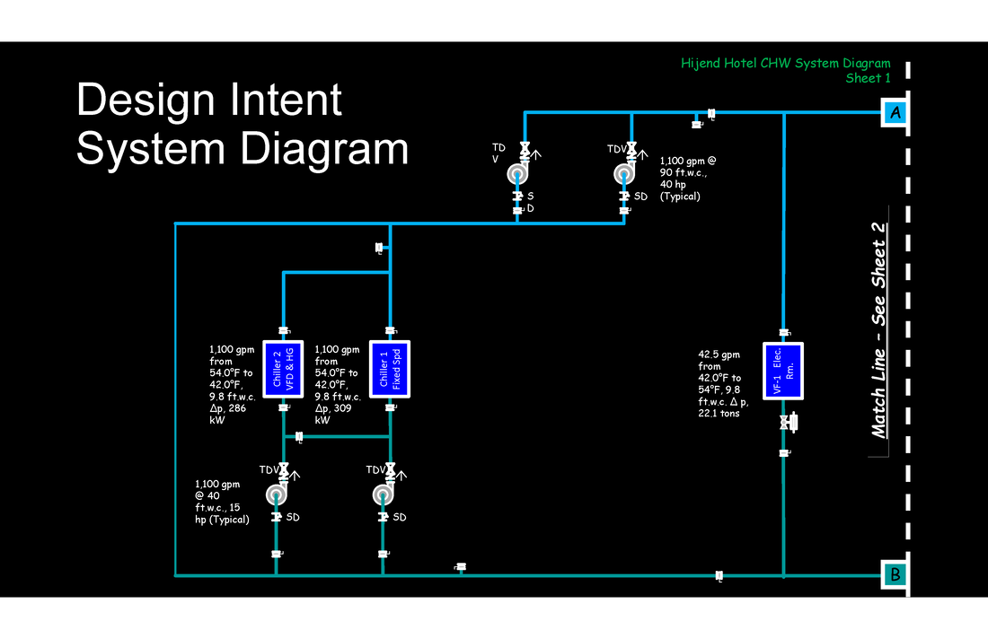
Hijend Hotel Chilled Water System Diagram Based On Project Documents
The files to the right are PowerPoint and .pdf versions of the central plant portion of the Hijend Hotel Chilled Water System diagram that Joe DeNuguy put together by reviewing the project documents. The diagram now needs to be field verified.
|
| ||||||||
The files below are the complete Hijend Hotel system diagram in case you are wondering what comes after the match line in the central plant portion above.
|
| ||||
Field Verified Hijend Hotel Chilled Water System Diagram
The files below are versions of Joe DeNuguy's Hijend Hotel chilled water system diagram with the central plant portion field verified. PowerPoint and .pdf versions are provided. The "black" versions include the entire system diagram with the central plant portion field verified. The "white" versions are just the field verified central plant version. The are provided in case you want to print them to draw on them for some of the exercises rather than working with them in PowerPoint.
|
| ||||||||
Hijend Hotel As Installed Central Plant CHW System Node Analysis
To answer some of the questions in the quiz, you had to do what many would call a node analysis. In HVAC systems, nodes are points in a system where several fluid streams come together to form a single stream or where a single stream splits into two or more separate streams.
Nerds, not to be confused with nodes, are people like me.
The tee where the bypass water mixes with the return water in the Hijend Hotel is an example of a node, as is the mixed air plenum on the Ball Room air handling system. For a node, the concepts of conservation of mass and energy apply (they also apply to nerds actually).
As a result, if you start with the somewhat scary steady flow energy equation and make some simplifying substitutions and assumptions that would apply to the tee in the plant's chilled water system, you can derive the following relationship.
As a side note, if you are wondering exactly what the simplifying assumptions and substitutions are, the derivation of the relationship above is nearly identical to the derivations illustrated for a mixed air plenum in this blog post.
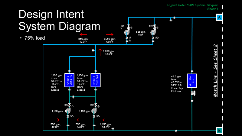
In any case, if you apply that concept to the Hijend Hotel central plant design intent system diagram and the as installed system diagram under the conditions specified in the quiz question, you will discover that what seems to be a minor difference in how the system was piped makes a significant difference in how it will operate at part load, primarily because of how it impacts the entering water temperature to the chillers as can be seen in the images below.
In any case, if you apply that concept to the Hijend Hotel central plant design intent system diagram and the as installed system diagram under the conditions specified in the quiz question, you will discover that what seems to be a minor difference in how the system was piped makes a significant difference in how it will operate at part load, primarily because of how it impacts the entering water temperature to the chillers as can be seen in the images below.
|

|
The files below take you to higher resolution versions if the images above. The PowerPoint files can also be edited if you want to try you hand at figuring out how the plants would work under other operating conditions, like one chiller at 75% load, etc.
|
| ||||||||
If you study the node analysis, you will realize that the design intent configuration preferentially loaded Chiller 1 when it was operating and put the part load on Chiller 2 if two chillers were on line. But as the system ended up being piped, if two chillers are online, they will simply split the load.
Preferentially loading chiller 1 and allowing chiller 2 to carry the load swings as important operational implications because of the kW per ton profile and part load capability of the chillers. Note that chiller 2 is equipped with a variable speed drive and hot gas bypass while chiller 1 is not.
Both chillers are nearly identical in terms of the evaporator and condenser tube bundles and their rated capacity. But because chiller 2 has a VFD, it is more efficient at part load that chiller 1, and it can also unload a bit more than chiller 1 before it will start to surge. But chiller 1 is actually more efficient at full load because it does not have the losses associated with a VFD.
The hot gas bypass system on chiller 2 allows it to unload even further, albeit in a very inefficient manner. So bottom line, the design intent configuration of the plant leveraged the capabilities of the different machines. The installed piping configuration does not allow that to happen when both chillers are operating.
If you wonder how things like this can happen, the third video at this link explains it. If you want to hone in on the details vs. watching the full video, which is a part of a series about how to develop a system diagram in the field, then use the table of contents to go to the sections titled "Value Engineering Revision" and "Why the Difference Happened".